Carrier head with non-contact retainer

a carrier head and retainer technology, applied in the direction of grinding drives, lapping machines, manufacturing tools, etc., can solve the problems of non-planar surface, non-uniform material removal, and non-uniformity on the substrate surfa

Inactive Publication Date: 2005-03-29
APPLIED MATERIALS INC
View PDF23 Cites 67 Cited by
  • Summary
  • Abstract
  • Description
  • Claims
  • Application Information

AI Technical Summary

Benefits of technology

Implementations of the invention may include one or more of the following features. A bottom surface of the lower projection may be separated from a top surface of a polishing pad by a gap. A housing portion may be secured to a drive shaft, and the base may be joined to the housing. The retaining ring may be vertically movable relative to the base. The base may include a flange which circumferentially surrounds the retaining ring. A second pressurizable chamber may be located between a top surface at the retaining ring and the base. Pressurization of the second pressurizable chamber may apply a downward second load to the retaining

Problems solved by technology

This nonplanar surface presents problems in the photolithographic steps of the integrated circuit fabrication process.
In general, uneven load distribution results in a non-uniform material removal and, consequently, in non-uniformity on the substrate surface.
A reoccurring problem in CMP is the so-called “edge effect”, i.e., the tendency of the substrate edge to be polished at a different rate than the

Method used


Image

  • Carrier head with non-contact retainer
  • Carrier head with non-contact retainer
  • Carrier head with non-contact retainer

Examples


Embodiment Construction

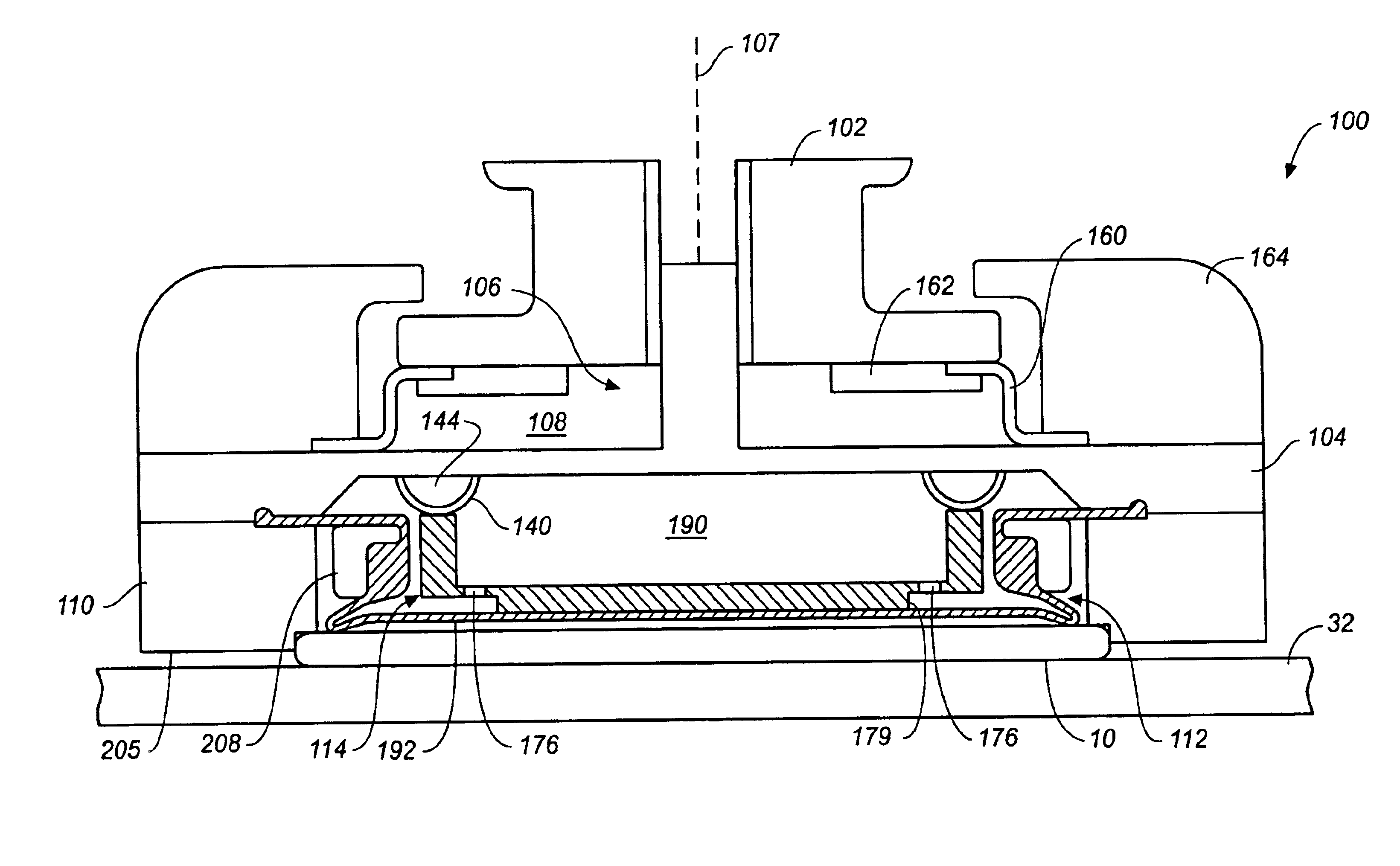
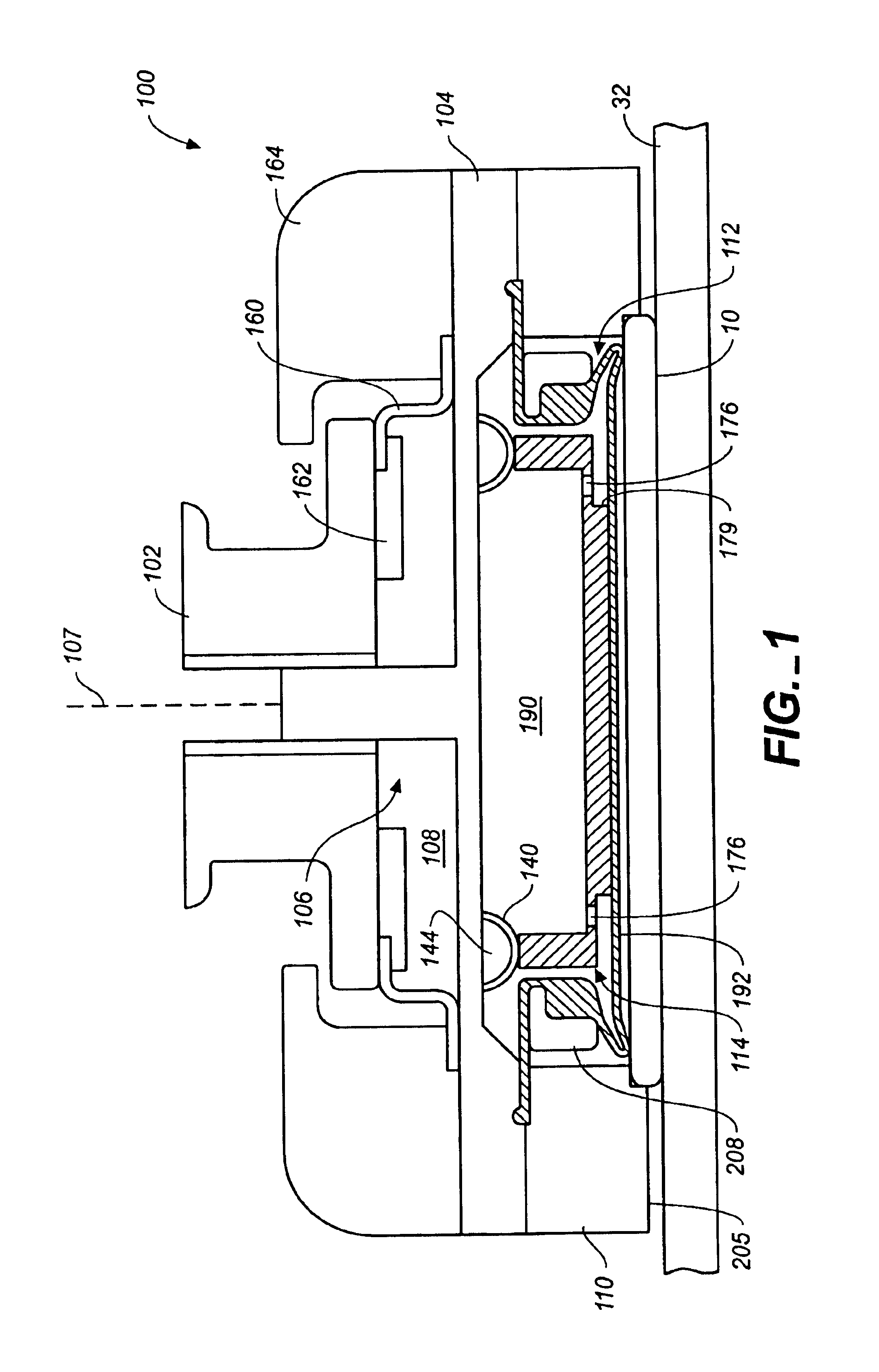
Referring to FIG. 1, a substrate 10 will be polished by a chemical mechanical polishing (CMP) apparatus that has a carrier head 100. A description of a suitable CMP apparatus may be found in U.S. Pat. No. 5,738,574, the entire disclosure of which is hereby incorporated by reference.

Referring to FIGS. 1 and 2, carrier head 100 includes a housing 102, a base 104, a gimbal mechanism 106 (which can be considered part of the base 104), a loading chamber 108, a retaining ring 110, and a substrate backing assembly 112. A description of a similar carrier head may be found in U.S. Pat. No. 6,183,354, the entire disclosure of which is incorporated herein by reference.

The housing 102 can be connected to a drive shaft to rotate therewith during polishing about an axis of rotation 107 which is substantially perpendicular to the surface of the polishing pad during polishing. The loading chamber 108 is located between the housing 102 and the base 104 to apply a load, i.e., a downward pressure, to ...


PUM


Abstract

A carrier head for chemical mechanical polishing of a substrate has a base and a retaining ring positioned beneath the base. The retaining ring includes a main portion with a first surface to apply a load to a perimeter portion of the back surface of the substrate and an annular projection with a second surface to retain the substrate. A bottom surface of the projection is separated from a top surface of a polishing pad by a gap.

Description

BACKGROUNDThe present invention relates generally to chemical mechanical polishing of substrates, and more particularly to a carrier head for chemical mechanical polishing.Integrated circuits are typically formed on substrates, particularly silicon wafers, by the sequential deposition of conductive, semiconductive or insulative layers. After each layer is deposited, it is etched to create circuitry features. As a series of layers are sequentially deposited and etched, the outer or uppermost surface of the substrate, i.e., the exposed surface of the substrate, becomes increasingly nonplanar. This nonplanar surface presents problems in the photolithographic steps of the integrated circuit fabrication process. Therefore, there is a need to periodically planarize the substrate surface.Chemical mechanical polishing (CMP) is one accepted method of planarization. This planarization method typically requires that the substrate be mounted on a carrier or polishing head. The exposed surface o...

Claims


Application Information

Patent Timeline
IPC IPC(8): B24B37/04B24B41/06
CPCB24B37/32B24B37/30
Inventor ZUNIGA, STEVEN M.
Owner APPLIED MATERIALS INC
Why Eureka
Try Eureka