Chuck apparatus

a chuck and chuck technology, applied in mechanical devices, manufacturing tools, transportation and packaging, etc., can solve the problems of troublesome operation and conventional chuck apparatus not being able to receive the second section of the tool bi

Inactive Publication Date: 2005-04-05
CHEN TSAI CHING
View PDF7 Cites 49 Cited by
  • Summary
  • Abstract
  • Description
  • Claims
  • Application Information

AI Technical Summary

Problems solved by technology

This operation is however troublesome.
This conventional chuck apparatus however cannot receive the second section of the tool bit.

Method used


Image

  • Chuck apparatus
  • Chuck apparatus
  • Chuck apparatus

Examples


Embodiment Construction

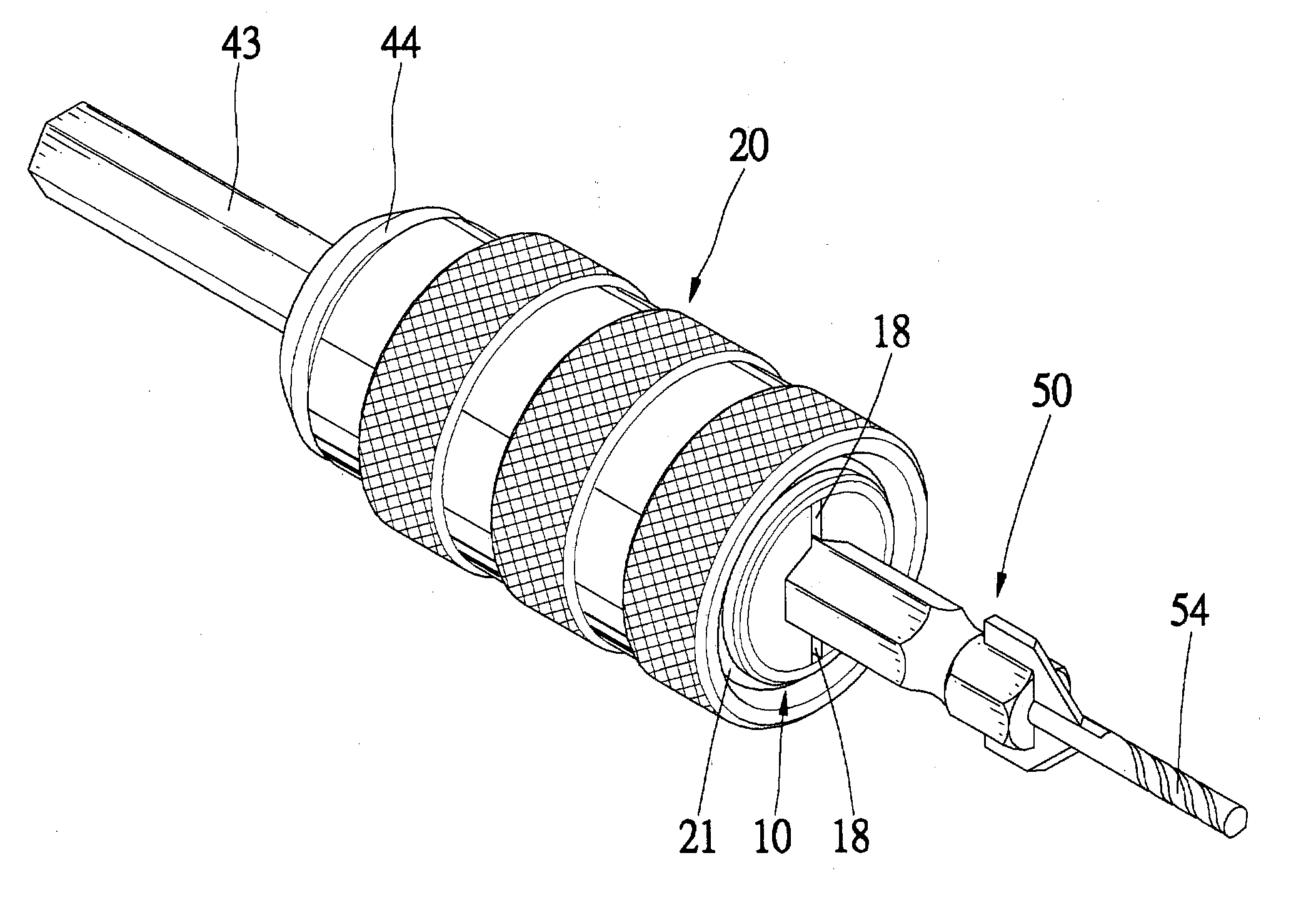
Referring to FIGS. 6˜11, a conventional tool bit 50 is shown. The tool bit 50 includes a first section for driving a screw and a second section for drilling a countersink hole. The second section of the tool bit 50 includes a drill 54 and two blades 52. The second section of the tool bit 50 includes a screwdriver 56. An annular groove 51 is defined in the tool bit 50 between the first and second sections.

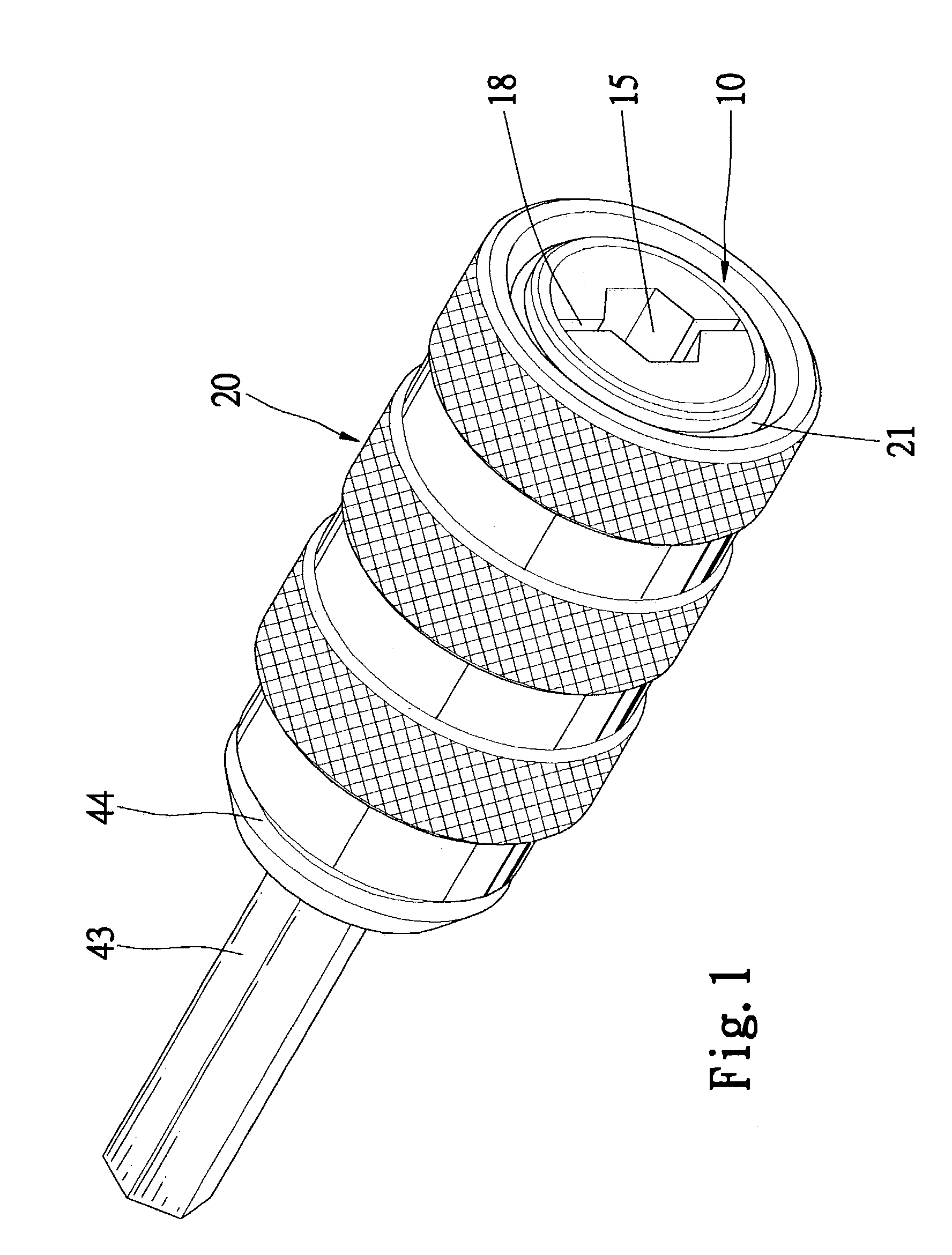
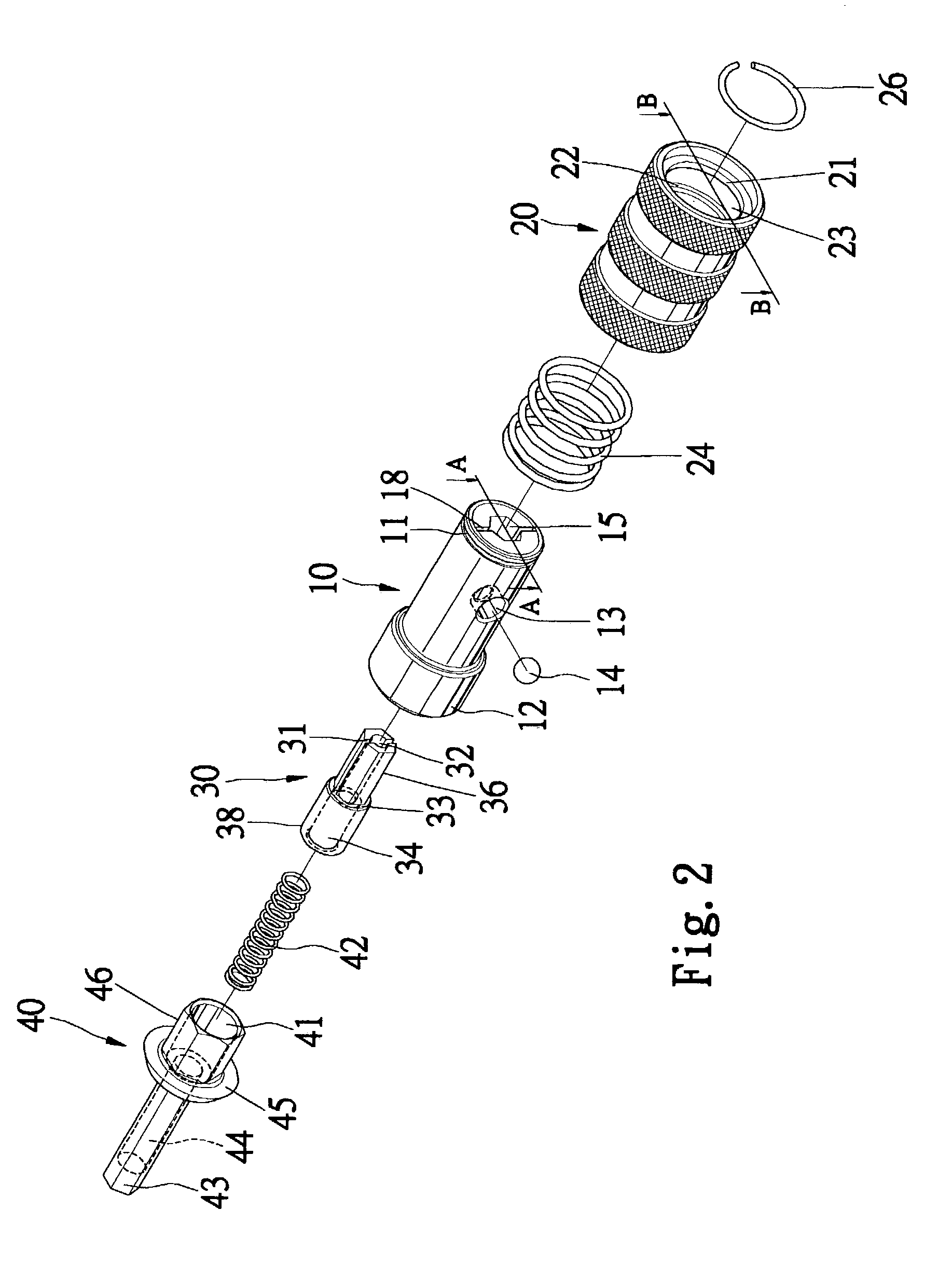
Referring to FIGS. 1 and 2, according to the preferred embodiment of the present invention, a chuck apparatus includes a socket 10, a collar 20, a spring 24, a pusher 30, a joint 40 and a spring 42.

Referring to FIG. 3, the socket 10 defines a first chamber 15, a second chamber 16 communicated with the first chamber 15 and a third chamber 17 communicated with the second chamber 16. An annular shoulder 19 is formed between the chambers 15 and 16. An annular shoulder 60 is formed between the chambers 16 and 17. A hole 13 is defined in the socket 10 and communicated with the first cham...


PUM


Abstract

A chuck apparatus is provided for holding a tool bit. The tool bit includes a drill, two blades, another working head and an annular groove defined therein. The chuck apparatus includes a socket, a ball detent, a collar and a joint. The socket defines an axial hole, a peripheral hole communicated with the axial hole and two slots for receiving the blades. The ball detent is put in the peripheral hole for insertion in the annular groove. The collar is movably mounted on the socket between a locking position for pushing the ball detent into the annular groove and a releasing position for allowing the ball detent to leave the annular groove. The joint includes a first section secured to the socket and a second section for connection with a motor.

Description

FIELD OF INVENTIONThe present invention relates to a chuck apparatus for holding a tool bit with a first section and a second section for drilling a countersink hole.BACKGROUND OF INVENTIONReferring to FIGS. 12 and 13, a conventional chuck apparatus including a socket 80 and a collar 90 movably mounted on the socket 80. The socket 80 includes a closed end for connection with a motor (not shown) and an open end for receiving a tool bit 94. A ball detent 92 is put in a hole (not numbered) transversely extending the socket 80. An internal edge of a ring 99 is put in an annular groove defined in an external face of the socket 80. The collar 90 defines, in an internal face, an annular groove 91 and an annular groove 96 separated from the annular groove 91 by means of an annular rib 97. A spring 93 is put in the annular groove 96, and compressed between the annular rib 97 and the ring 82. A ring 98 is fit in the collar 90 for abutment against the ring 82, thus avoiding the collar 90 escap...

Claims


Application Information

Patent Timeline
Patent Type & Authority Patents(United States)
IPC IPC(8): B23B31/10B23B31/107B23B51/10B25B21/00B25B23/00
CPCB23B31/1071B23B51/108B25B21/007B25B23/0035Y10T279/3481Y10T408/953Y10T279/17752Y10T279/17008
Inventor CHEN, TSAI-CHINGCHANG-KAO, CHIU-MAN
Owner CHEN TSAI CHING
Why Eureka
Try Eureka