Laser display system

a display system and laser technology, applied in the field of laser display systems, can solve the problems of deteriorating picture quality, lowering contrast ratio and resolution,

Inactive Publication Date: 2005-04-05
LG ELECTRONICS INC
View PDF5 Cites 89 Cited by
  • Summary
  • Abstract
  • Description
  • Claims
  • Application Information

AI Technical Summary

Benefits of technology

The technical effect of this patent is that it describes how to improve the quality of images produced by a laser display system. By adjusting the way in which the laser light is shone onto the screen, researchers have been able to reduce the appearance of small bumps or blurbs called “specks” that can make some screens look less than perfect. This change in technique helps create smoother and more accurate visual displays.

Problems solved by technology

The technical problem addressed in this patent text relates to improving the performance of laser display systems which use a laser as a light source. These systems often suffer from poor picture quality caused by the generation of specks or spots on the screen resulting from the interference of the laser's coherence properties. This can reduce the contrast ratio and resolution of the images being displayed.

Method used


Image

  • Laser display system
  • Laser display system
  • Laser display system

Examples


first embodiment

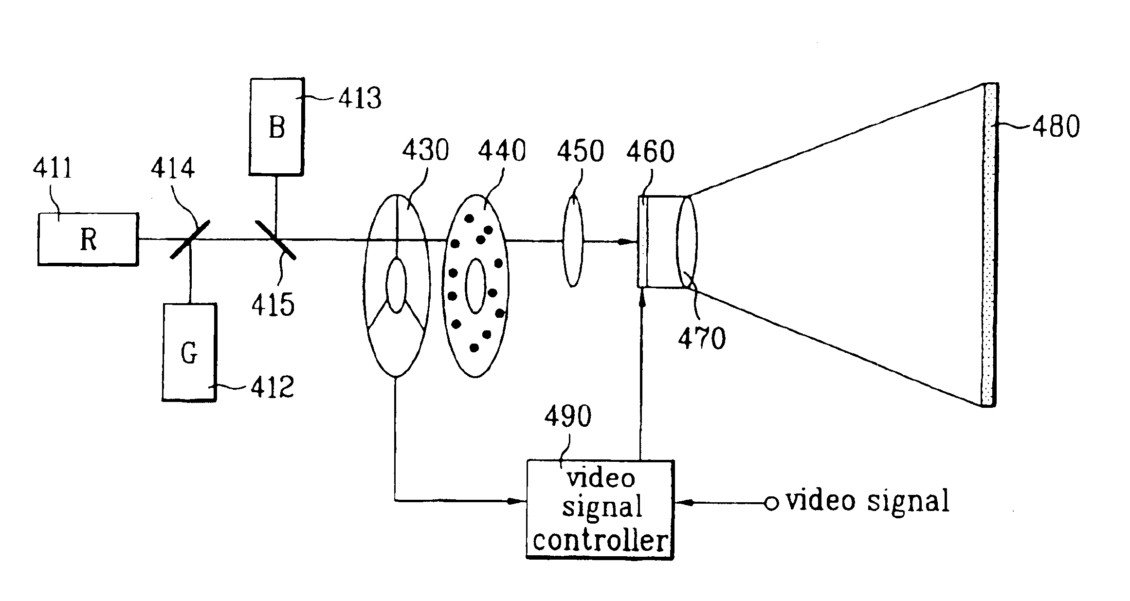
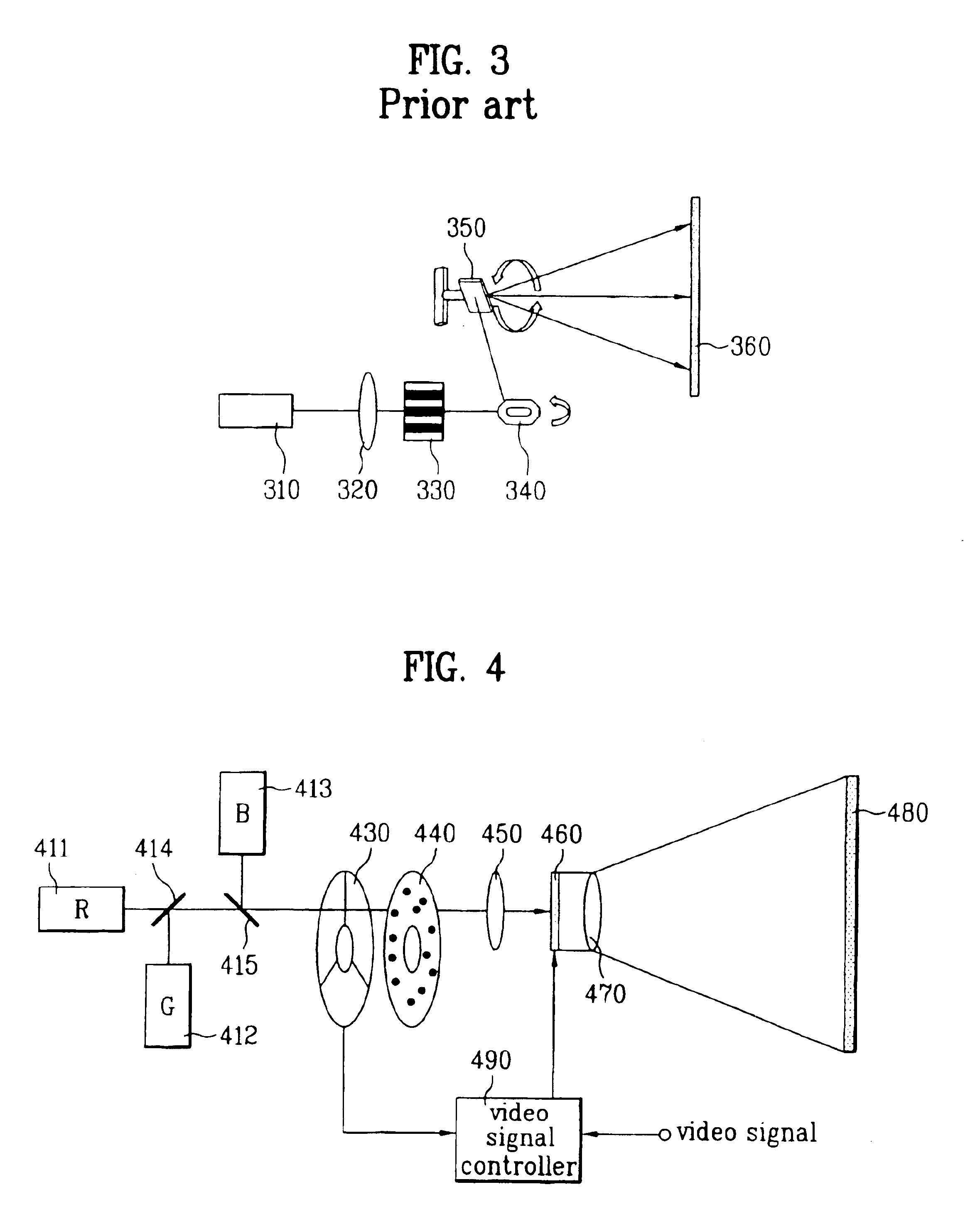
FIG. 4 is a structure view illustrating a laser display system according to the first embodiment of the present invention.

As shown in FIG. 4, the laser display system according to the first embodiment of the present invention includes a Red laser generating red light 411, a Green laser 412 generating green light, a Blue laser 413 generating blue light, first and second filters 414 and 415 mixing light by transmitting or reflecting a particular wavelength of red, green and blue light, a rotation color separator 430 separating the mixed light to red, green and blue light sequentially, a diffuser 440 diffusing the separated light, an illuminating device 450 irradiating a display panel 460 with the light from the diffuser 440, the display panel generating an image by modulating transmittance of the light from the illuminating device by receiving a video signal from a controller 490, a projector 470 enlarging and projecting the image, a screen 480 displaying the enlarged image, and the c...

second embodiment

FIG. 8 is a structure view illustrating a laser display system according to the second embodiment of the present invention.

Referring to FIG. 8, the laser display system according to the second embodiment of the present invention includes a Red laser 811 generating red light, a Green laser 812 generating green light, a Blue laser 813 generating blue light, a diffuser 820 diffusing the red, green and blue light, an illuminating device 830 irradiating a display panel 840 with the diffused light, the display panel generating an image by modulating transmittance of the light from the illuminating device 830 by receiving a video signal from a controller 870, a projector 850 enlarging and projecting the image, a screen 860 displaying the enlarged image, and the controller sequentially turning on / off the lasers 811, 812 and 813 of the corresponding color after receiving and separating the video signal into the red, green and blue color signals.

An operation of the laser display system accord...


PUM


Abstract

A laser display system is disclosed, to remove speckles displayed on a screen, which includes at least one laser as light source, at least one filter transmitting or reflecting a particular wavelength of red, green and blue light generated in the laser, and mixing the light red, green and blue light to one; a rotation color separator separating the mixed light into the red, green and blue light sequentially; a diffuser diffusing the separated light; an illuminating device irradiating with the light progressed from the diffuser; a display panel generating an image by modulating transmittance of the light from the illuminating device according to an electric signal of a video signal; and a controller receiving the video signal, and making correspondence of color areas from the rotation color separator and the display panel.

Description


Claims


Application Information

Patent Timeline
Owner LG ELECTRONICS INC
Why Eureka
Try Eureka