Method for despeckling in laser display systems

a laser display and laser technology, applied in non-linear optics, instruments, optics, etc., can solve problems such as random phase retardation, and achieve the effects of low operating voltage, high transparence, and high efficiency

Active Publication Date: 2015-06-23
JABIL CIRCUIT INC
View PDF7 Cites 1 Cited by
  • Summary
  • Abstract
  • Description
  • Claims
  • Application Information

AI Technical Summary

Benefits of technology

[0009]The inventive optical devices employ liquid crystal layers and introduce random phase modulation or beam shifting to eliminate the speckles in laser display systems. In a first embodiment, the liquid crystal layer is built in a single cell with a size larger than the laser beam. No pixilated structures are involved and therefore much less diffraction or scattering loss of laser light occurs, thereby providing high efficiency.
[0014]More particularly, in the first embodiment, a liquid crystal cell is formed by vertically oriented liquid crystal molecules and randomly oriented liquid crystal molecules. The liquid crystal cell is disposed in sandwiched relation between an input electrode and a ground electrode and a first and a second glass cover are disposed in overlying relation to the input and ground electrodes, respectively. The liquid crystal cell is larger than a laser beam in size so that a laser beam follows a path of travel through the device. Diffraction and scattering loss of light are substantially eliminated in the absence of pixel structures.
[0020]A sixth embodiment includes a first field-induced gradient index prism disposed between a first input electrode and a first ground electrode so that when voltage is applied to the electrodes an electric field is at a maximum strength at the first input electrode and drops gradually towards zero (0) at the first ground electrode. A second field-induced gradient index prism is disposed between a second input electrode and a second ground electrode so that when voltage is applied to said second electrodes an electric field is at a maximum strength at the second input electrode and drops gradually towards zero (0) at the second ground electrode. The first and second field-induced gradient index prisms are disposed in opposing relation to one another so that a thickest end of the first field-induced gradient index prism is aligned with a thinnest end of the second field-induced gradient index prism. A laser beam that follows a first path of travel that intersects the device at a ninety degree) (90°) angle when no voltage is applied to the electrodes is shifted slightly from the first path of travel when voltage is applied to the electrodes. Rapid application and removal of a voltage to the electrodes substantially eliminates speckles from the laser beam.
[0024]It includes at least a first and a second device for reducing speckles in the system. The first and second devices are disposed parallel to one another and perpendicular to a path of travel of a laser beam so that multi-function and high-speed modulation is provided to eliminate speckles in laser-illuminated display systems.
[0027]Yet another object is to solve said problem with high transparence and high efficiency.
[0028]Still further objects are to solve said problem with a low power consumption device that is compact, simple, and that has a low cost when produced in high volume.

Problems solved by technology

This causes random phase retardation due to the birefringence of the liquid crystal material and also introduces random phase modulation across the input laser beam.

Method used


Image

  • Method for despeckling in laser display systems
  • Method for despeckling in laser display systems
  • Method for despeckling in laser display systems

Examples


Embodiment Construction

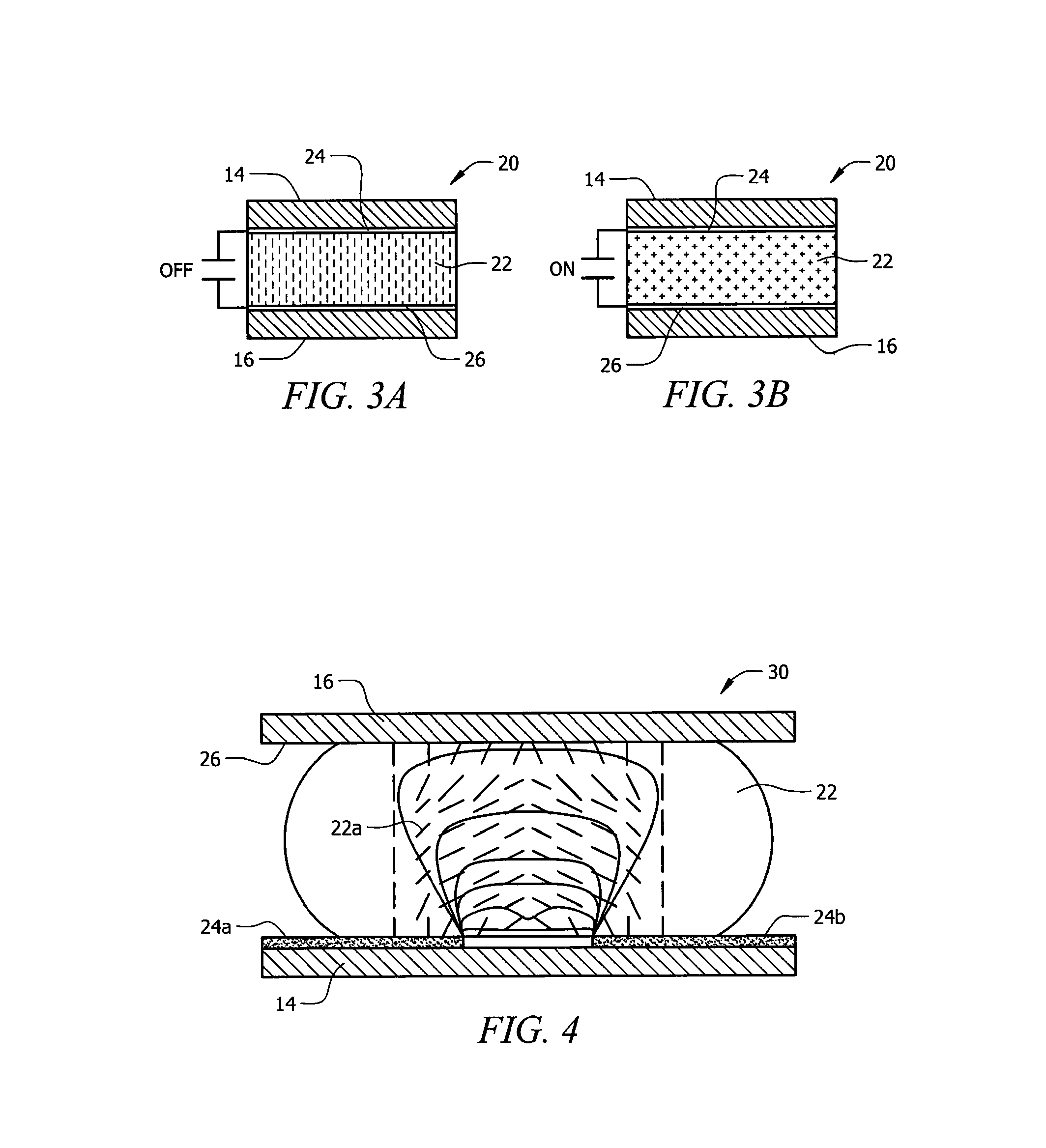
[0049]The text accompanied by FIGS. 1-4 relates to the subject of phase modulation across the beam.

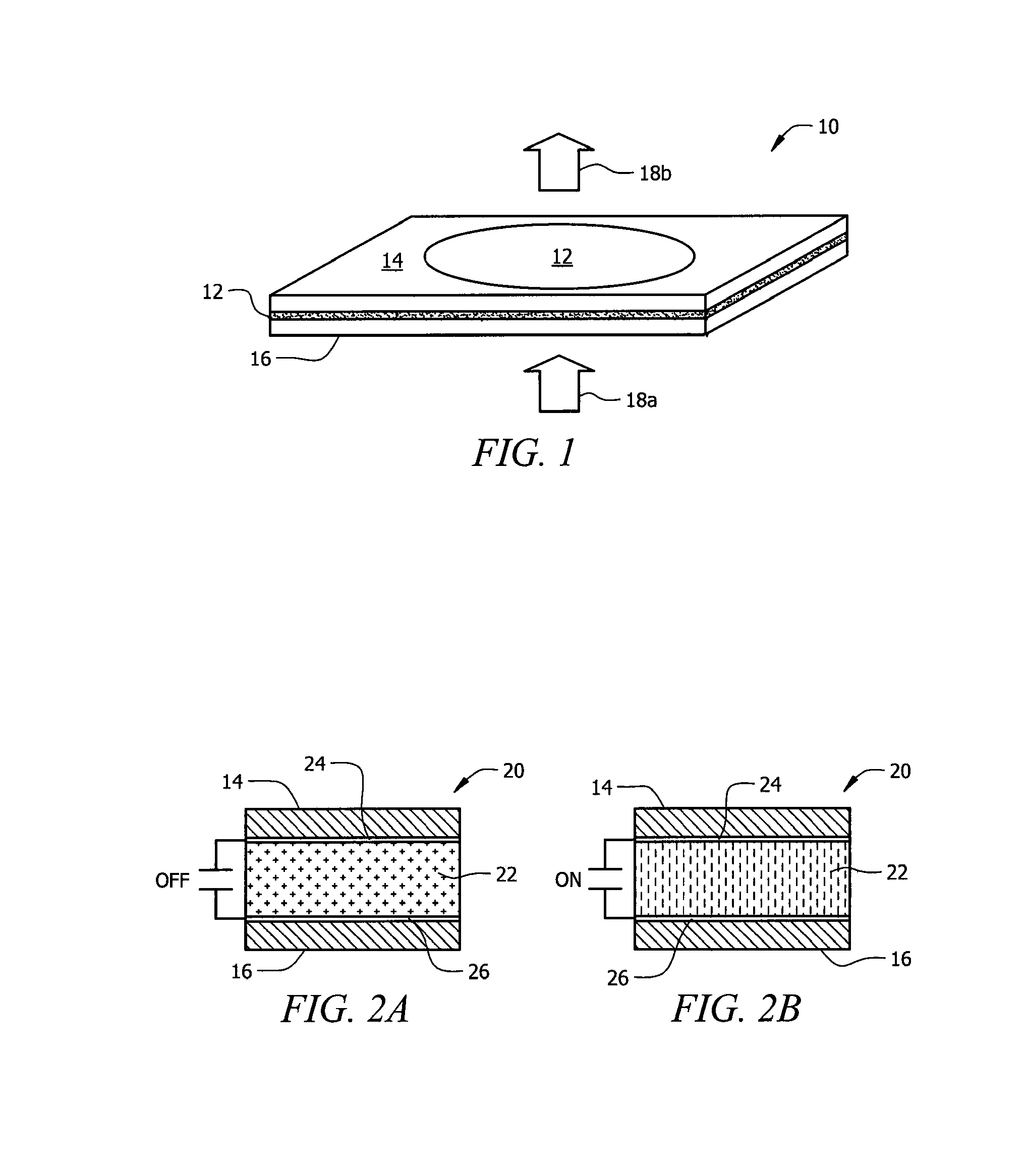
[0050]Referring now to FIG. 1, it will there be seen that an illustrative embodiment of the invention is denoted as a whole by the reference numeral 10.

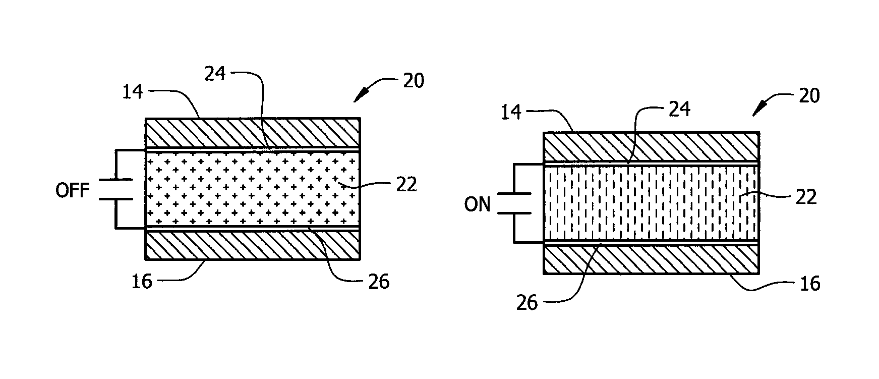
[0051]Apparatus 10 removes speckles by randomly varying the phase or waveform across a laser beam. A single liquid crystal cell 12 is positioned between two (2) glass substrates 14, 16, both of which have flat surfaces. The liquid crystal molecules of liquid crystal cell 12 are either randomly or vertically oriented. Cell 12 is larger in size than input laser beam 18a and therefore no pixel structures are required to eliminate or substantially inhibit diffraction or scatter loss of laser light. The output laser beam is denoted 18b. There are no alignment layers; accordingly, the need for a polyimide rubbing process is also eliminated. The input and ground electrodes that sandwich the liquid crystal layer in FIG. 1 are not depicted to si...


PUM

PropertyMeasurementUnit
angleaaaaaaaaaa
angleaaaaaaaaaa
angleaaaaaaaaaa

Abstract

A device used in laser display systems for despeckling includes a liquid crystal cell disposed in sandwiched relation between an input and a grounded electrode. A glass cover overlies each electrode. In a first embodiment, the cell may include vertically or randomly oriented liquid crystal molecules and the liquid crystal cell is larger than a laser beam in size for random phase modulation or retardation. Light loss due to diffraction and scattering are substantially eliminated in the absence of pixel structures. In another embodiment, the input electrode is divided into two separate parts. Vertically aligned liquid crystal molecules rotate and follow field fringes created by applying a first voltage to the input electrodes. Additional embodiments include a device that has two wedge-shaped liquid crystal layers, a device that includes plural field-induced gradient index prisms, a device including a tilted mirror, and composite devices.

Description

CROSS-REFERENCE TO RELATED APPLICATIONS[0001]This application is a divisional of U.S. patent application Ser. No. 12 / 052,377, filed Mar. 20, 2008, entitled “APPARATUS FOR DESPECKLING IN LASER DISPLAY SYSTEMS,” which claims the benefit of U.S. Provisional Application Ser. No. 60 / 895,933, filed Mar. 20, 2007, entitled “APPARATUS FOR DESPECKLING IN LASER DISPLAY SYSTEMS.” The aforementioned related applications are hereby incorporated by reference.FIELD OF THE INVENTION[0002]This invention relates, generally, to image projection systems that use lasers as an illumination source. More particularly, this invention relates to an apparatus that inhibits the speckling caused by lasers in such image projection systems.DESCRIPTION OF THE PRIOR ART[0003]The high coherence of laser light causes the speckle phenomenon in laser-illuminated systems. Speckle appears as a stationary pattern of light with dark spots superimposed over a viewable image.[0004]One prior art device includes high speed rot...

Claims


Application Information

Patent Timeline
Patent Type & Authority Patents(United States)
IPC IPC(8): G02F1/135G02F1/13G02F1/1337
CPCG02F1/1313G02F2001/133738G02F2203/03G02F1/133738
Inventor LI, LINMOREJON, ISRAEL J.ZHAI, JINHUIO'SULLIVAN, EVAN
Owner JABIL CIRCUIT INC
Why Eureka
Try Eureka