Collimating plate, lighting apparatus and liquid crystal display apparatus

Inactive Publication Date: 2005-04-05
FUJIFILM CORP +1
View PDF9 Cites 87 Cited by
  • Summary
  • Abstract
  • Description
  • Claims
  • Application Information

AI Technical Summary

Benefits of technology

The present invention has been accomplished under these circumstances. It is a first object of the present invention to provide a collimating plate possessing an excellent collimating capability, that can issue a collimated light which has a high luminance and is of good directivity; a lighting apparatus provided

Problems solved by technology

On the other hand, they have poor viewing angle characteristics (narrow viewing angle) since as the viewing direction or angle changes, the contrast of an image degrades sharply and the gradation also reverses to have the image look differently.
As a result, depending on a position of a viewer, the image can not be viewed correctly.
In medical applications described above, diagnosis with monitors is based on the difference in image density, so that not only is it required to produce an image of high contrast ratio but at the same time, incorrect or improper recognition of an image can cause wrong diagnosis or inconsistency in the results of diagn

Method used


Image

  • Collimating plate, lighting apparatus and liquid crystal display apparatus
  • Collimating plate, lighting apparatus and liquid crystal display apparatus
  • Collimating plate, lighting apparatus and liquid crystal display apparatus

Examples


Example

A collimating plate, a lighting apparatus and a liquid crystal display apparatus according to the present invention are described below in detail with reference to the preferred embodiments shown in the accompanying drawings.

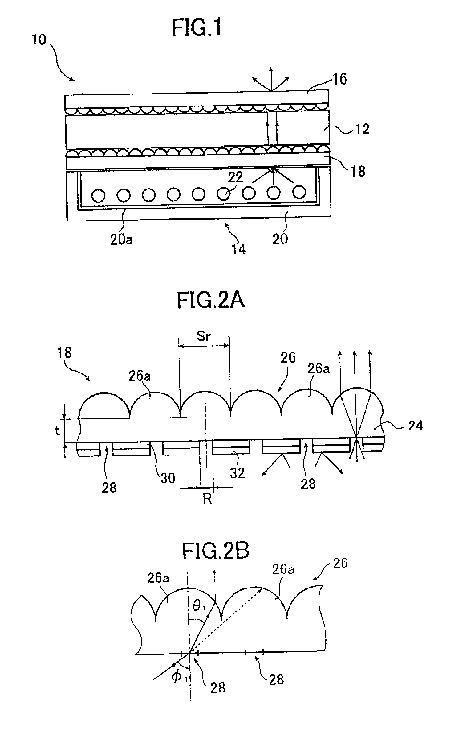
FIG. 1 shows an embodiment of a liquid crystal display apparatus according to the sixth aspect of the present invention in conceptual form.

The liquid crystal display apparatus (hereinafter referred to as. display apparatus) generally indicated by 10 in FIG. 1 is a so-called liquid crystal display (hereunder referred to as LCD) that utilizes a liquid crystal display panel 12 as an image display device. It comprises the liquid crystal display panel 12, a backlight section 14 that causes collimated light (parallel light) to be incident on the liquid crystal display panel 12 and a light diffusing plate 16 that diffuses an image-bearing light which has passed through the liquid crystal display panel 12.

In the illustrated case, the liquid crystal display panel 12 is c...


PUM


Abstract

The light collimating plate includes a lens substrate, a plurality of microlenses disposed on a surface of the lens substrate, a plurality of light entrance areas, each having a circular or rectangular form a center of which is on an optical axis of the microlens, and a light shield layer formed on another surface of the lens substrate, and covering other area than the light entrance areas. When n and t are a refractive index and a thickness of the lens substrate, respectively, and C (R; diameter, A, B; sides of rectangle) is a size of light entrance area, a size of the microlens Sr satisfies the following formula in the light collimating plate: Sr≧2t×tan θ+C (with the proviso that θ=sin−1 (1/n)). Or, a form of the microlens in the light collimating plate is a part of an ellipsoid shown in the following formula X2/a2+y2/a2+z2/c2=1 (x and y represent axis on the surface of the lens substrate, z represents the optical axis), it's accentricity ε is shown in the following formula ε=(c2−a2)1/2/c=1/n and it's far focal point is on a position of the light entrance area. The lighting apparatus and the liquid crystal display apparatus use the light collimating plate.

Description

BACKGROUND OF THE INVENTIONThe present invention relates to the technical field of increasing a range of viewing angles in liquid crystal display devices. More particularly, the present invention relates to a collimating plate having a high or an excellent collimating capability, a lighting apparatus which is provided with such a collimating plate, and a liquid crystal display apparatus comprising such a lighting apparatus, which all effecting the increase in a range of viewing angles in the liquid crystal display.The opportunity or the frequency of use of liquid crystal displays (LCDs) as a display for word processors and computers is rapidly increasing today. The use of LCDs as a monitor in ultrasonic, CT and MRI diagnostic apparatus is under review. Conventionally, these medical diagnostic apparatus have primarily used CRTs (cathode-ray-tubes) as a monitor.LCDs have many advantages such as ease in size reduction, small thickness and lightweightness. On the other hand, they have p...

Claims


Application Information

Patent Timeline
IPC IPC(8): F21V8/00G02B27/00G02B3/00G02F1/1335G02F1/13G02F1/13357
CPCG02B3/0031G02B3/0056G02B3/04G02F1/133611G02B6/0053G02F2001/133607G02F1/133504G02F1/133526G02F1/133607
Inventor YAMAGUCHI, AKIRA
Owner FUJIFILM CORP
Why Eureka
Try Eureka