Partial discharge monitoring apparatus and partial discharge remote monitoring system for rotating electric machines

Inactive Publication Date: 2005-01-20
MITSUBISHI ELECTRIC CORP
View PDF2 Cites 28 Cited by
  • Summary
  • Abstract
  • Description
  • Claims
  • Application Information

AI Technical Summary

Benefits of technology

[0016] The present invention is intended to solve the aforementioned problems of the prior art. It is an object of the invention to provide a compact partial discharge monitoring apparatus having an excellent noise-removing capability. It is a more specific object of the invention to provide a compact partial discharge monitoring apparatus which can detect pulses with high resolution and reduce the number of detected pulses, wherein each pulse is detected by using two frequency

Problems solved by technology

However, the apparatus shown in Japanese Laid-open Patent Publication No. 2002-71742 has a problem that the apparatus can not remove noise components falling within the passband of the narrowband filter.
A shortcoming of the apparatus of Japanese Patent Publication No. 3187642 is that the apparatus becomes too large and too expensive if this apparatus is to be used for detecting such a large number of partial discharges with high resolution and for transferring data for the purpose of remote monitoring operation.
Further, the apparatus shown in Japanese Patent Publication No. 2751834 has a wide detecting frequency band, so that this apparatus has a problem that it can not remove noise components falling within this frequency band.
Generally, noise pulses occur in extraordinarily l

Method used


Image

  • Partial discharge monitoring apparatus and partial discharge remote monitoring system for rotating electric machines
  • Partial discharge monitoring apparatus and partial discharge remote monitoring system for rotating electric machines
  • Partial discharge monitoring apparatus and partial discharge remote monitoring system for rotating electric machines

Examples


Example

First Embodiment

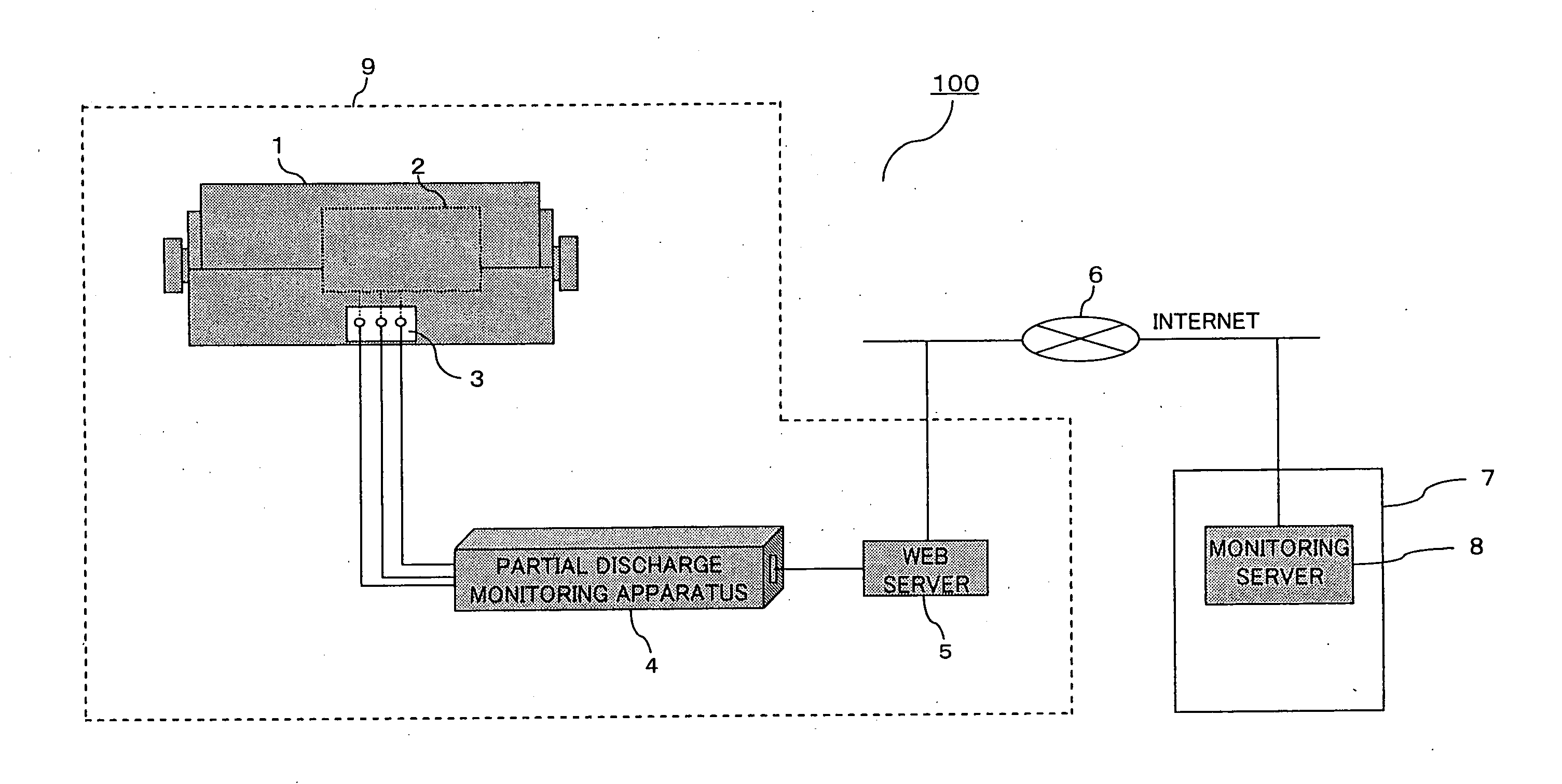
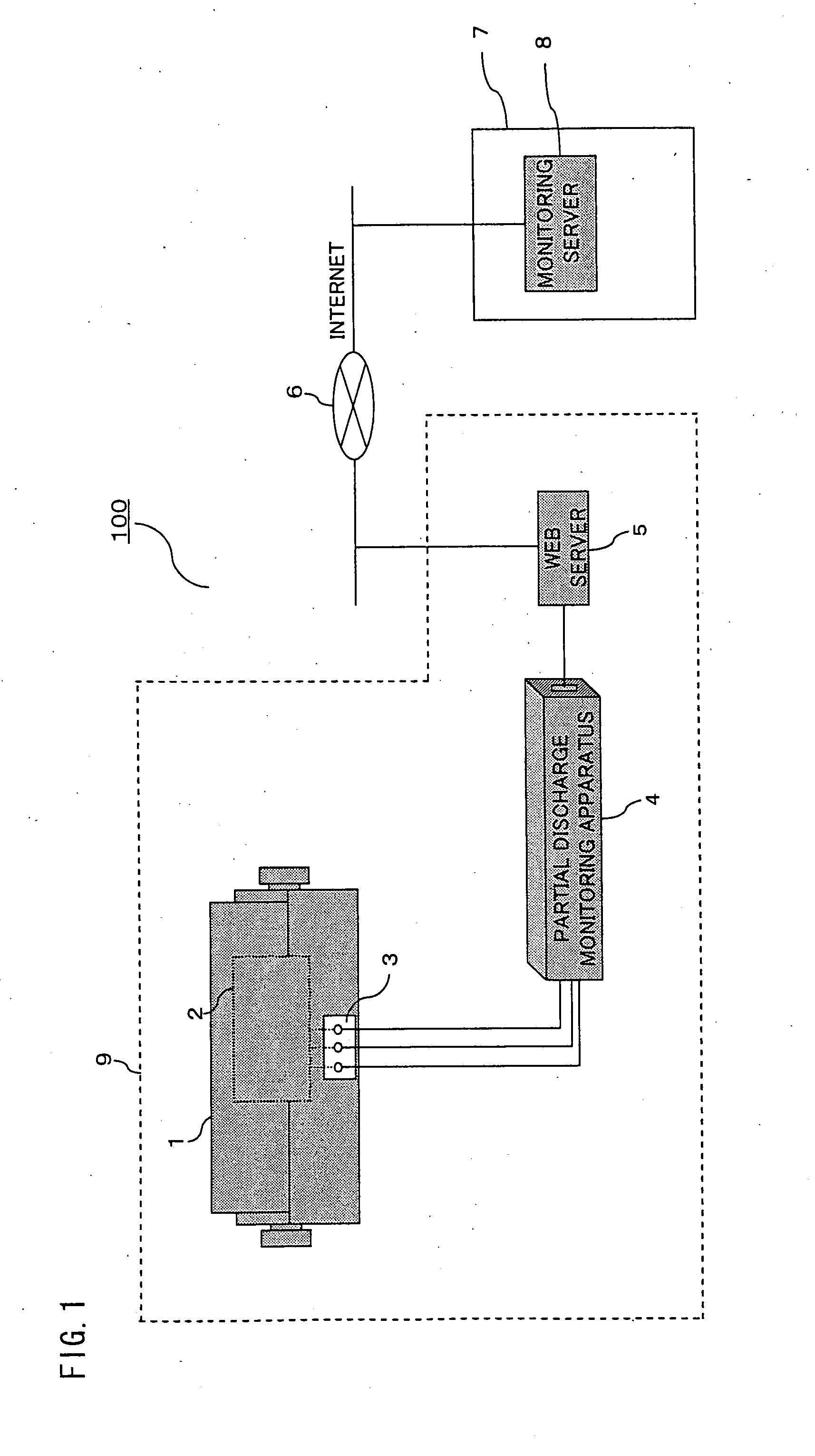
[0032]FIG. 1 is a diagram showing the configuration of a partial discharge remote monitoring system 100 for explaining a partial discharge monitoring apparatus 4 according to a first embodiment of the invention. The partial discharge remote monitoring system 100 is, for example, a system for remotely monitoring the state of insulation of a rotating electric machine 1, such as a turbine generator, installed in a thermal power plant 9. In this system, signals output from partial discharge sensors 2 which are located in the rotating electric machine 1 are led to the exterior of the generator through a terminal box 3 and input into the partial discharge monitoring apparatus 4. The partial discharge monitoring apparatus 4 transmits and receives information to and from a monitoring server 8 located at a supervisory control center 7 which performs centralized supervisory control of various devices installed in multiple power plants, for example, via a web server 5 and the ...

Example

Second Embodiment

[0061]FIG. 9 is a flowchart showing an automatic measurement range setting procedure of a second embodiment by which the measurement range is automatically set in accordance with detected signal levels. The controller CPU 22 automatically sets the attenuator 14a for the frequency band f1 by the following operation flow.

[0062] Step 1: Signals are measured for 1 second.

[0063] Step 2: The controller CPU 22 stores measured data in the RAM 19.

[0064] Step 3: The controller CPU 22 reads out the data stored in the RAM 19.

[0065] Step 4: The controller CPU 22 removes noise by the aforementioned two-frequency correlation noise removal method of the first embodiment.

[0066] Step 5: The controller CPU 22 determines the level at which partial discharge pulses occur at a frequency of 60 pps where the commercial frequency is 60 Hz (50 pps where the commercial frequency is 50 Hz) by calculation.

[0067] Step 6: The controller CPU 22 compares the level of 60 pps with a 40% level ...

Example

Third Embodiment

[0083] A third embodiment of the invention employs a configuration which makes it possible to vary the signal detection levels 33 of the peak hold circuits 17a, 17b based on partial discharge data obtained in the aforementioned measurement range setting procedure. Here, the most preferable ratio of varying the signal detection level 33 is 50% of the value of the signal detection level 33 at which partial discharges are detected at a frequency of 60 pps. If the value of the signal detection level 33 at which partial discharges are detected at a frequency of 60 pps is 70 mV when the measurement range is 0 to 100 mV, for example, the signal detection level 33 is set to 35 mV so that pulses lower than 35 mV would not be peak-held. In a case where partial discharges occur intermittently and the levels of the detected pulses exceed the measurement range at a frequency of 10 pps, the controller CPU 22 alters the value of the signal detection level 33 (which is 40 mV in thi...


PUM


Abstract

A partial discharge monitoring apparatus for a rotating electric machine includes a partial discharge detecting circuit which measures each signal output from a partial discharge sensor located in the rotating electric machine simultaneously in a first frequency band and a second frequency band. Detection time for detecting each signal includes a peak hold time and a dead time, which comes after the peak hold time. A next-occurring signal is detected after the dead time has elapsed.

Description

BACKGROUND OF THE INVENTION [0001] 1. Field of the Invention [0002] The present invention relates to a partial discharge monitoring apparatus and a partial discharge remote monitoring system for monitoring partial discharges occurring in rotating electric machines. [0003] 2. Description of the Background Art [0004] Partial discharge monitoring apparatuses for detecting and monitoring partial discharges occurring in rotating electric machines, such as turbine generators, are conventionally known. [0005] One example of such a partial discharge monitoring apparatus is disclosed in Japanese Laid-open Patent Publication No. 2002-71742, in which partial discharges are measured by a single-channel detecting circuit which limits a detecting range by using a narrowband filter to remove noise components existing outside the passband of the narrowband filter. [0006] Another example of a partial discharge monitoring apparatus is proposed in Japanese Patent Publication No. 3187642. The partial d...

Claims


Application Information

Patent Timeline
IPC IPC(8): G01R31/12G01R31/34
CPCG01R31/343G01R31/1227
Inventor KANEDA, YOSHIHARUKAWASE, CHIHARU
Owner MITSUBISHI ELECTRIC CORP
Why Eureka
Try Eureka