Disk drive and method of detecting servo address mark in the same

a technology of servo data and disk drive, applied in the field of disk drive, can solve the problems of not determining whether actual or virtual servo data is first detected, and not ensuring that a target type of servo data is detected

Inactive Publication Date: 2005-04-05
KK TOSHIBA
View PDF11 Cites 80 Cited by
  • Summary
  • Abstract
  • Description
  • Claims
  • Application Information

AI Technical Summary

Benefits of technology

[0015]The accompanying drawings, which are incorporated in and constitute a part of the specification, illustrate presently preferred embodiments of the invention, and together with the general description given above and the detailed description of the embodiments given below, serve to explain the principles of the invention.

Problems solved by technology

However, if the same servo address marks are applied to both actual and virtual servo data, it is impossible to determine whether actual or virtual servo data is first detected, when a servo address mark is detected.
Further, it is not ensured that a target type of servo data, i.e. either actual servo data or virtual servo data is detected as a result of the first servo data search.
However, also with this method, it is not ensured that the target type of servo data is detected as a result of the first servo data search.

Method used


Image

  • Disk drive and method of detecting servo address mark in the same
  • Disk drive and method of detecting servo address mark in the same
  • Disk drive and method of detecting servo address mark in the same

Examples


Embodiment Construction

IC that is applied in a second modification of this embodiment;

[0022]FIG. 7 is a block diagram showing a configuration of an R / W channel IC that is applied in a third modification of this embodiment;

[0023]FIG. 8 is a block diagram showing a configuration of an R / W channel IC that is applied in a fourth modification of this embodiment; and

[0024]FIG. 9 is a block diagram showing a configuration of an R / W channel IC that is applied in a fifth modification of this embodiment.

DETAILED DESCRIPTION OF THE INVENTION

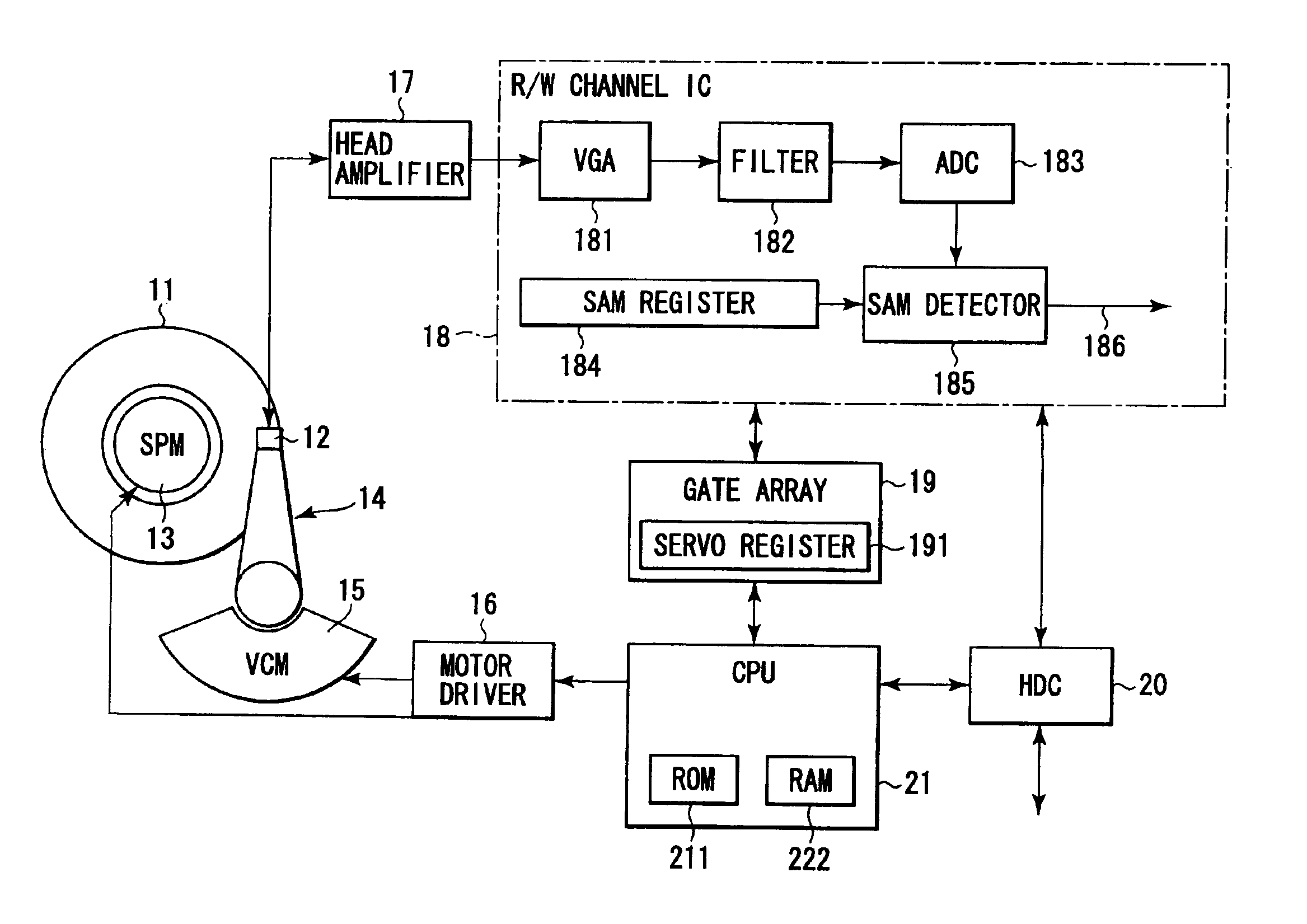
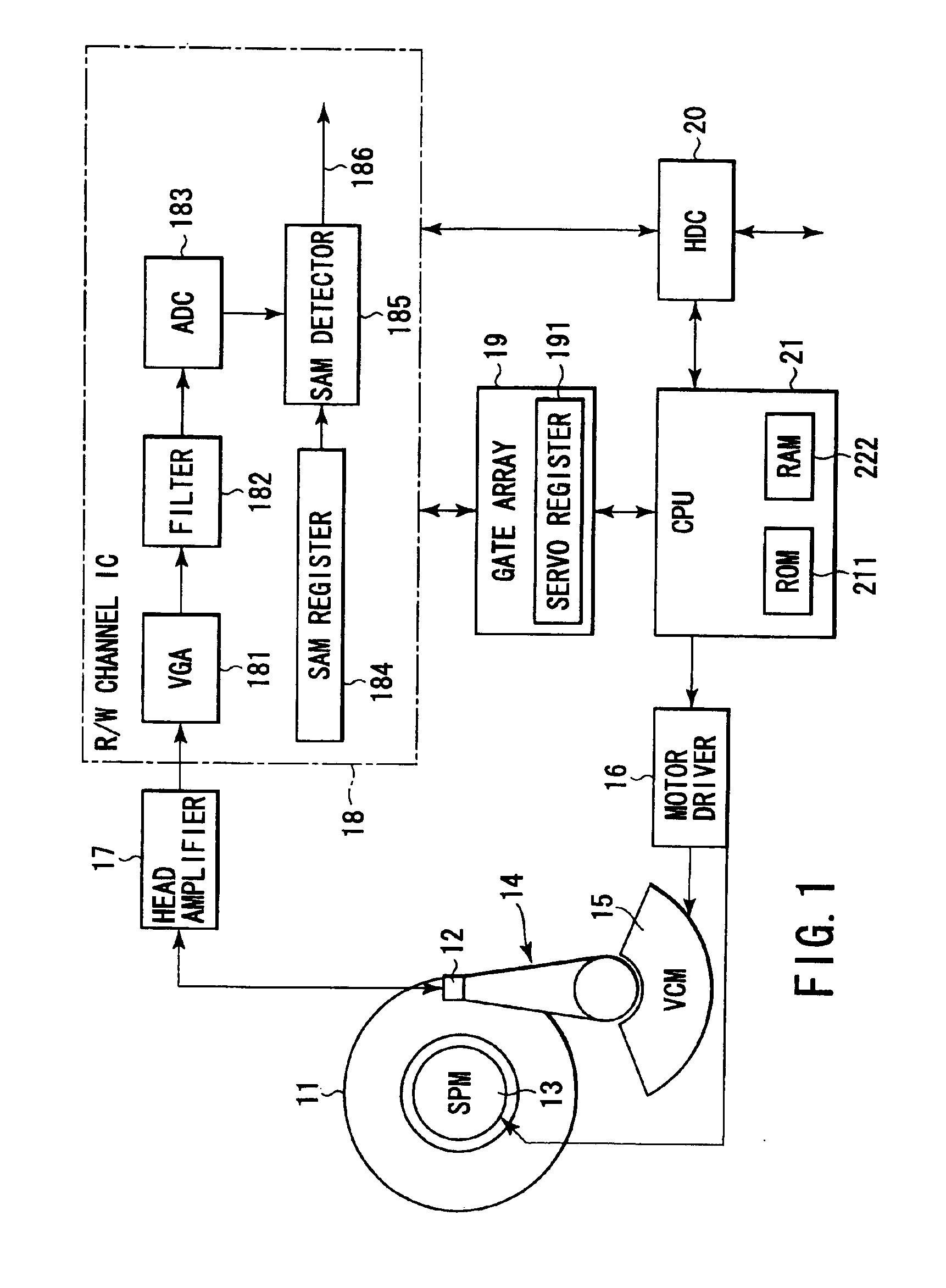
[0025]The present invention will be described below in conjunction with its embodiment, with reference to the drawings. FIG. 1 is a block diagram showing a configuration of a magnetic disk drive according to an embodiment of the present invention. In a magnetic disk drive (hereinafter referred to as an “HDD”), a disk (magnetic disk) 11 is a recording medium having two disk surfaces, i.e. a top surface and a bottom surface. At least one of top and bottom surfaces of the disk (magn...


PUM

PropertyMeasurementUnit
distanceaaaaaaaaaa
densityaaaaaaaaaa
mechanical accuracyaaaaaaaaaa

Abstract

A detector detects, in read data, a servo address mark of a type indicated by a register. Every time a SAM is detected during a self servo process, a CPU carries out tracking control in accordance with corresponding servo data. The CPU causes a head to write a corresponding type of additional servo data item in a disk at a position offset from the position of servo data containing the detected SAM, by a predetermined distance in a circumferential direction of the disk. Every time sets of servo data, each consisting of various types of data items, are written in the disk, the head is moved by a predetermined pitch in a radial direction of the disk.

Description

CROSS-REFERENCE TO RELATED APPLICATIONS[0002]This application is based upon and claims the benefit of priority from the prior Japanese Patent Application No. 2002-254125, filed Aug. 30, 2002, the entire contents of which are incorporated herein by reference.BACKGROUND OF THE INVENTION[0003]1. Field of the Invention[0004]The present invention relates to a disk drive that utilizes a composite head to execute a self servo write process to arrange plural sets of servo data in a circumferential direction of a disk, each set containing plural types of servo data each containing a unique type of servo address mark. In particular, the present invention relates to a disk drive suitable for detecting a target type of servo data in the disk as well as a method of detecting a servo address mark in the disk.[0005]2. Description of the Related Art[0006]Magnetic disk drives that use a disk (disk medium) as a recording medium are well known. Magnetic disk drives, notably small-sized magnetic disk d...

Claims


Application Information

Patent Timeline
Patent Type & Authority Patents(United States)
IPC IPC(8): G11B5/596G11B5/55G11B21/10
CPCG11B5/59605G11B5/5526
Inventor KOYANAGI, TAKAHIRO
Owner KK TOSHIBA
Why Eureka
Try Eureka