Porous duct configured with a thin film

a thin film, air intake duct technology, applied in the direction of combustion-air/fuel-air treatment, intake silencers for fuel, machines/engines, etc., can solve the problems of air entering the cylinders after permeating the porous wall, affecting the power and torque performance of the engine, and causing load loss, etc., to achieve economic and simple manufacturing

Inactive Publication Date: 2005-04-12
WECOSTA
View PDF6 Cites 10 Cited by
  • Summary
  • Abstract
  • Description
  • Claims
  • Application Information

AI Technical Summary

Benefits of technology

Having regard to the fact that large portions of the surface of the film are not fixed onto the porous wall, the film does therefore not completely lay against the porous wall and may thus move under the influence of aerial pulses within the duct. The film is a minimal obstructions to the propagation of waves pulsed through the porous wall by way of its lightness and, especially, its capacity to move. In effect, the aim is to strictly limit the role of this film to that of a fluid barrier.
According to a particularly advantageous embodiment of the present invention, which is economical and simple to manufacture, the film is fixed to the porous wall by means of welding or gluing and, preferably, by means of ultrasonic welding.

Problems solved by technology

However, air intake ducts configured with porous walls according to the known prior art feature many disadvantages.
The warm air arriving within the cylinders after permeating the porous wall is detrimental to the power and / or torque performance of the engine.
Secondly, ducts with porous walls of the known art feature some coarseness, from which a loss of load arises by means of the ducted air rubbing against the coarse wall thereof.
Finally, it is necessary to include a very wide plastic oversleeve in such air intake ducting systems in order to obtain a sufficient imperviousness when immersed in water, which is very detrimental from an acoustical and style point of view, as well as with regard to the thermal ageing of the plastic material.
Alternatively, it is imperative to soak the fibrous material forming the porous wall with a fluoride-based resin, which is an expensive and complicated solution from an industrial point of view and does not provide a uniform imperviousness over all the areas of the duct wall.

Method used


Image

  • Porous duct configured with a thin film
  • Porous duct configured with a thin film

Examples


Embodiment Construction

FIG. 1

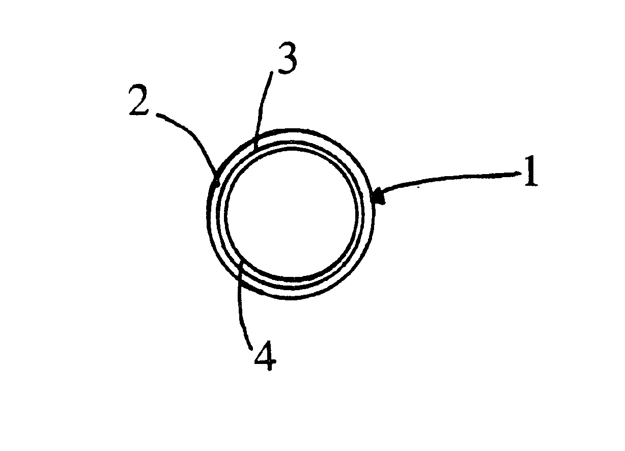
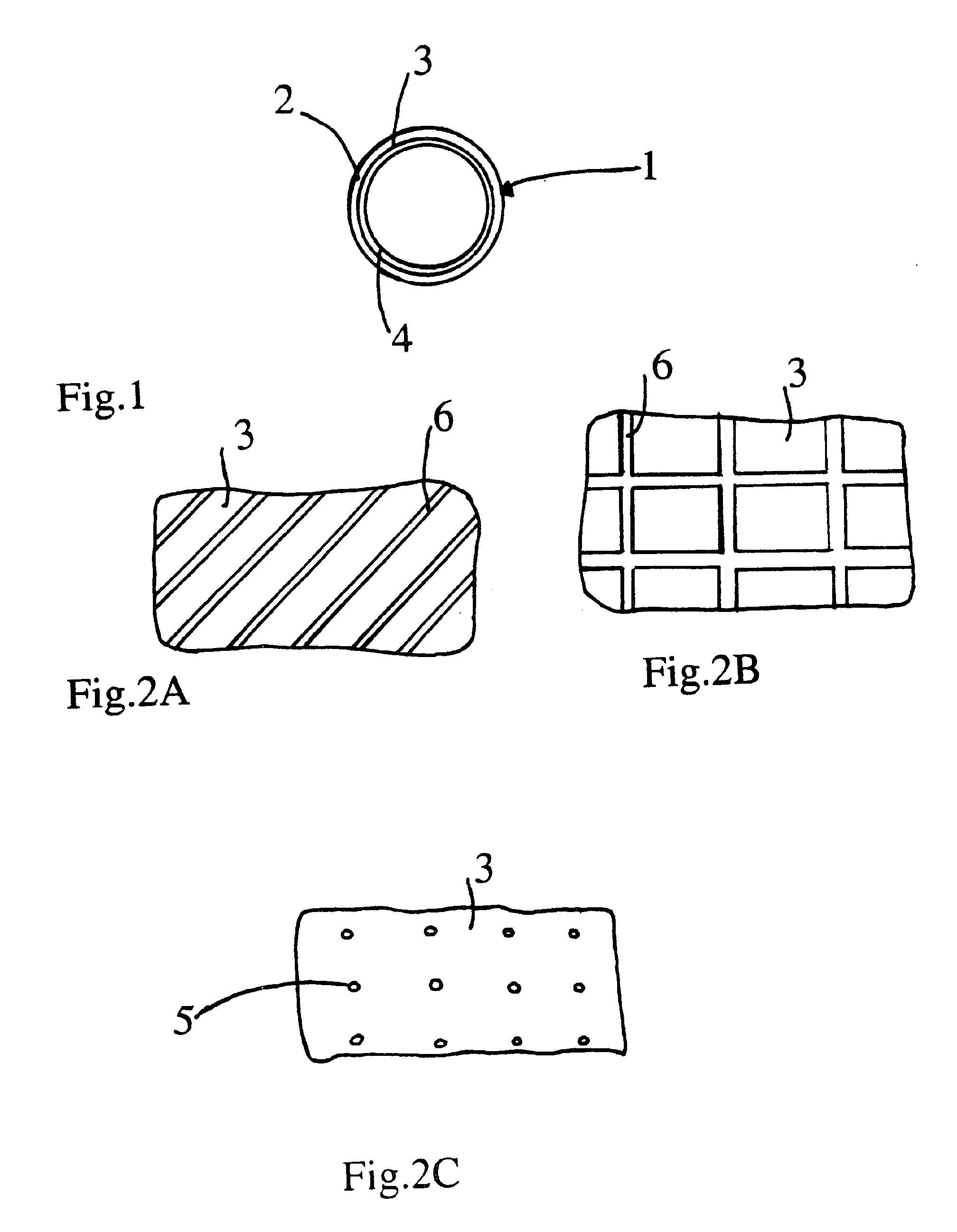
In FIG. 1, the air intake duct 1 of an internal combustion engine provides air to be combusted within the internal combustion engine. The duct is shown in the figure with a tubular shape and comprises a first tubular wall 2 made of a porous material, i.e. having openings through which fluids may pass, wherein the material maybe any of the following: open-cell foam, woven fabric or nonwoven fabric.

The thickness of the porous wall generally lies between one millimeter and three millimeters. The diameter of the porous wall generally lies between forty millimeters and seventy millimeters. A film 4 made of a plastic material is fixed to the internal surface 3 of the tubular wall 2, wherein the material is notably in polyethylene, polypropylene, polyamide, polyester, or another. The film made of plastic material is for instance configured with a thickness of 30 im.

Such a thickness is sufficiently thin for avoiding any incidence of the film of plastic material upon the accoustical ch...


PUM


Abstract

An intake duct 1 is provided, particularly for taking air in an internal combustion engine, notably the engine of an automobile. The duct includes a first wall 2 made of a porous material, wherein a film 4 is implemented which is sufficiently thin for avoiding any incidence upon the acoustical characteristics, having notably a surface mass of less than 100 grams per square meter. The film 4 is fixed onto the porous wall 2 such that at least 50% of the surface of the film facing the porous wall 2 is not fixed thereto.

Description

BACKGROUND OF THE INVENTION1. Field of the InventionThe present invention relates to air intake ducts. More particularly, the present invention relates to intake ducts for the combustion air of an internal combustion engine in an automobile.2. Description of the Related ArtAir intake ducts configured with a porous wall are known according to the known prior art. The porous walls provide for better acoustic characteristics because the acoustical resonance of the air column delimited by the porous wall are largely dampened, unlike known plastic ducts with rigid and impervious walls. Indeed, pulses corresponding to the resonance frequencies within the air column may propagate to the outside by traversing the porous wall, which diminishes the intensity of the respective pressure and speed antinodes.However, air intake ducts configured with porous walls according to the known prior art feature many disadvantages. Firstly, the porous wall is permeable to the warm air located for instance ...

Claims


Application Information

Patent Timeline
Patent Type & Authority Patents(United States)
IPC IPC(8): F02M35/12F02M35/10F02M35/024
CPCF02M35/1277F02M35/1272F02M35/024
Inventor LEPOUTRE, HENRI
Owner WECOSTA
Why Eureka
Try Eureka