Milling head for thread whirling

a technology of thread whirling and milling head, which is applied in the direction of shaping cutters, manufacturing tools, mechanical equipment, etc., can solve the problems of difficult and time-consuming process of head b>10/b>

Inactive Publication Date: 2005-04-12
REM SALES
View PDF54 Cites 71 Cited by
  • Summary
  • Abstract
  • Description
  • Claims
  • Application Information

AI Technical Summary

Problems solved by technology

However, setting the circular cutting elements 12 in proper cutting position in the milling head 10 is a difficult and a time consuming process that requires special tools such as a setting gauge, a setting jig, and a knock out device.

Method used


Image

  • Milling head for thread whirling
  • Milling head for thread whirling
  • Milling head for thread whirling

Examples


Embodiment Construction

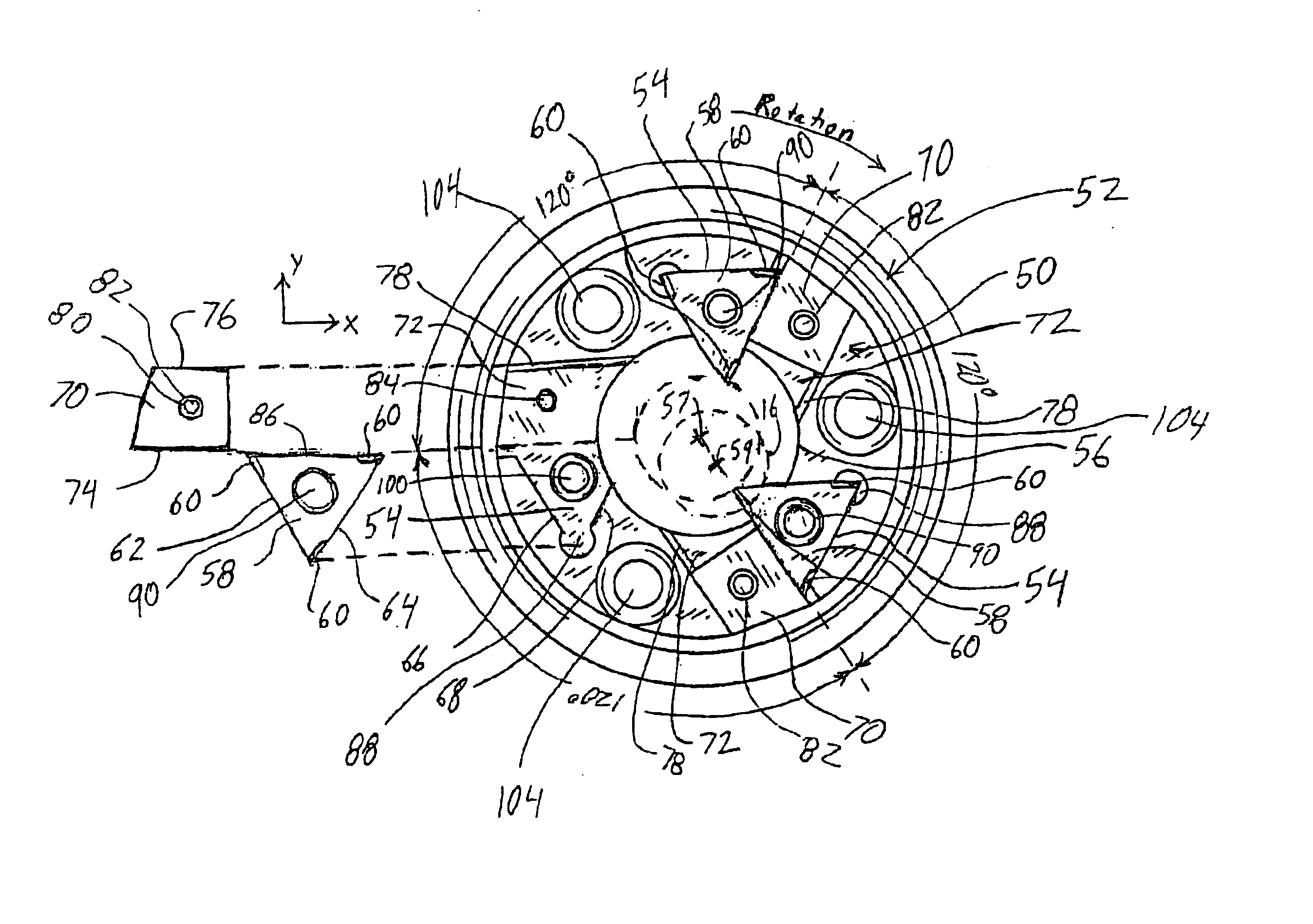
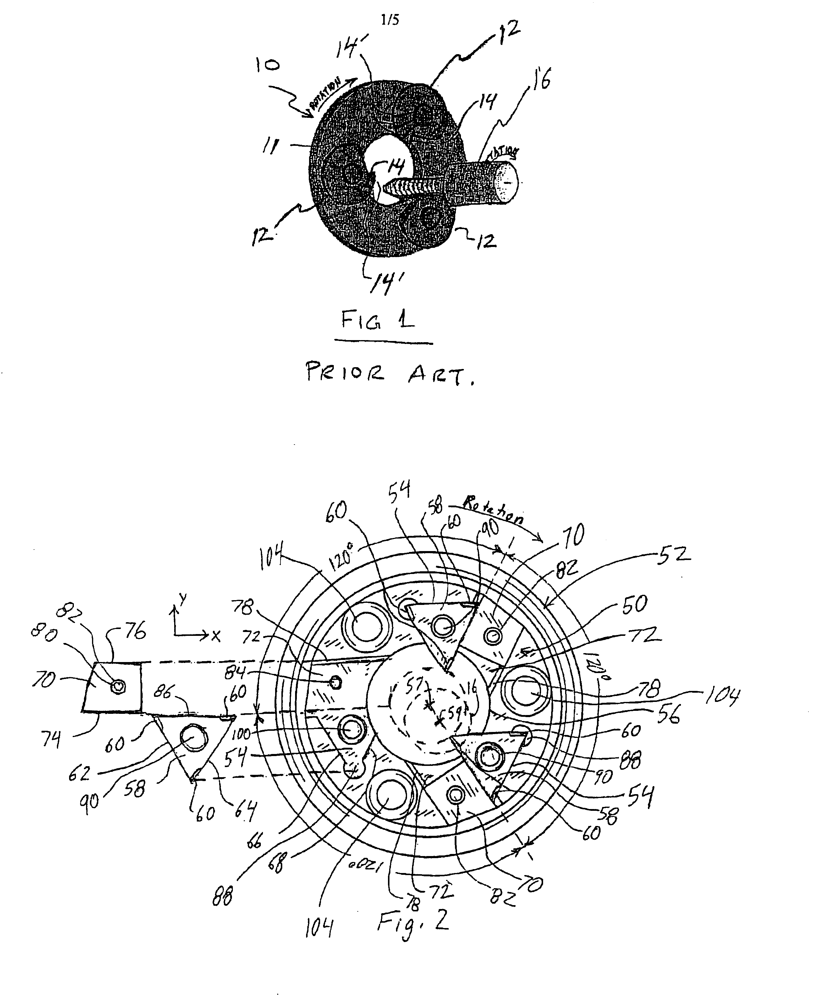
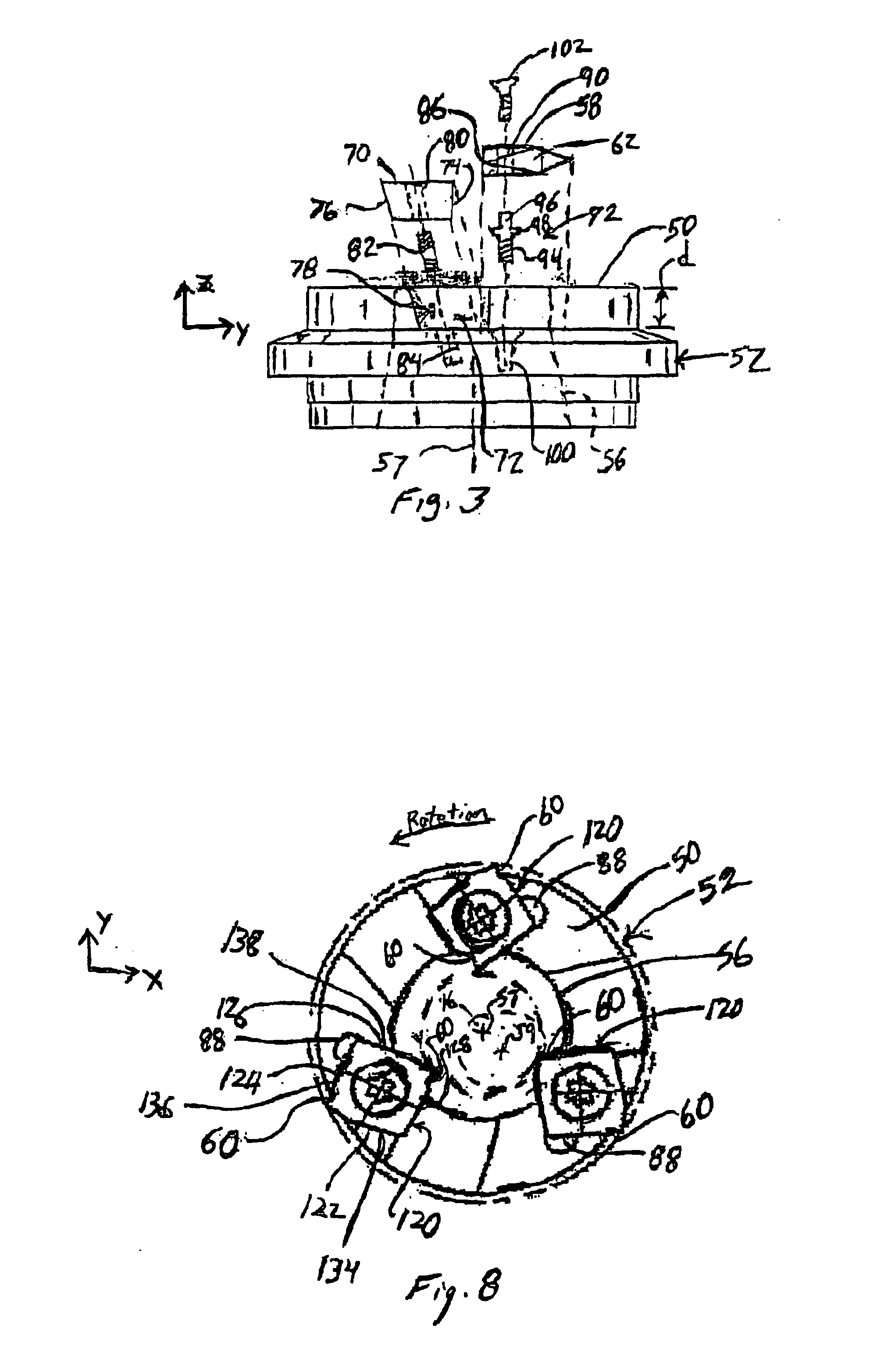
Referring to FIG. 2, a face 50 formed on a hollow milling head 52 for thread whirling is shown. Face 50 includes a series of recesses 54 formed thereon and evenly spaced around a center hole 56. Center hole 56 is centered at the axis of rotation 57 of the milling head 52 to accommodate the work-piece 16, which has an axis of rotation as indicated at 59. Disposed within each recess 54 is a removable cutting element 58. In the embodiment illustrated, three recesses 54 and three cutting elements 58 are shown, but there may be provided more or less recesses 54 and cutting elements 58 if desired. Each cutting element 58 includes a plurality of interchangeable cutting surfaces 60 formed thereon, and sides 62 and 64 of each cutting element 58 contact walls 66 and 68 of the recess 54 to align one of the cutting surfaces 60 in a desired cutting position with respect to the hollow milling head 52. In the embodiment shown, each cutting element 30 is triangular in shape. However, any convenient...


PUM

PropertyMeasurementUnit
clearance angleaaaaaaaaaa

Abstract

A milling head for thread whirling, the milling head includes a plurality of cutting elements evenly disposed around a center hole, each cutting element in the plurality of cutting elements includes at least two cutting surfaces formed thereon. Any one of the at least two cutting surfaces is selectable to extend within the center hole for contacting a work-piece. Each cutting element in the plurality of cutting elements is disposed in a recess formed in a face of the milling head, with each recess defining at least two walls. Each of the at least two walls contacts a side of the cutting element to align the cutting element in a predetermined relationship with respect to the milling head. In one embodiment, the plurality of cutting elements include first and second sets of cutting elements. The first set of cutting elements is evenly disposed around the center hole and contact the work-piece to produce a thread form on the work-piece. The second set of cutting elements is evenly disposed around the center hole and contacts the work-piece to remove material proximate the outside diameter of the work-piece.

Description

BACKGROUNDThe present invention relates to the machining of threads and, more particularly, to the machining of threads by thread whirling.Thread whirling is a cutting process performed on a lathe, milling machine, or dedicated thread whirling machine, in which a thread is produced on the outside diameter of metallic or non-metallic material (work-piece). The shape to be imposed is produced by cutting elements (tools) mounted within a hollow milling head (tool holder ring), which rotates around the outside diameter of the work-piece. The work-piece may be rotated in the same direction as the milling head and at a relatively lower speed. The axis of rotation of the work-piece is offset from the axis of rotation of the milling head, and the axis of rotation of the milling head is tilted at the desired helix angle of the thread. The work-piece is fed along its axis of rotation through the milling head, or the milling head moves along the axis of rotation of the work-piece. The work-pie...

Claims


Application Information

Patent Timeline
Patent Type & Authority Patents(United States)
IPC IPC(8): B23G5/18B23G1/00B23G1/34B23G5/00
CPCB23G1/34B23G5/18B23G2200/10Y10T409/30056Y10T407/1938Y10T409/302744B23G2240/60
Inventor GAINER, RONALD JOHN
Owner REM SALES
Why Eureka
Try Eureka