Connector

a connector and bracket technology, applied in the direction of coupling device connection, coupling parts engagement/disengagement, electrical apparatus, etc., can solve the problem of difficult operation of detachment, and achieve the effect of efficient detachment of the connector from the brack

Inactive Publication Date: 2005-04-12
SUMITOMO WIRING SYST LTD +1
View PDF8 Cites 7 Cited by
  • Summary
  • Abstract
  • Description
  • Claims
  • Application Information

AI Technical Summary

Benefits of technology

The present invention was developed in view of the above problem and an object thereof is to efficiently detach a connector from a bracket.

Problems solved by technology

However, depending on the disposed position of the bracket, the detaching operation is very difficult to carry out because an operator has to feel for it without being able to see and / or has only a narrow space for hands.

Method used


Image

  • Connector
  • Connector
  • Connector

Examples


Embodiment Construction

Referring now to the accompanying drawings, a description will be given in detail of preferred embodiments of the invention.

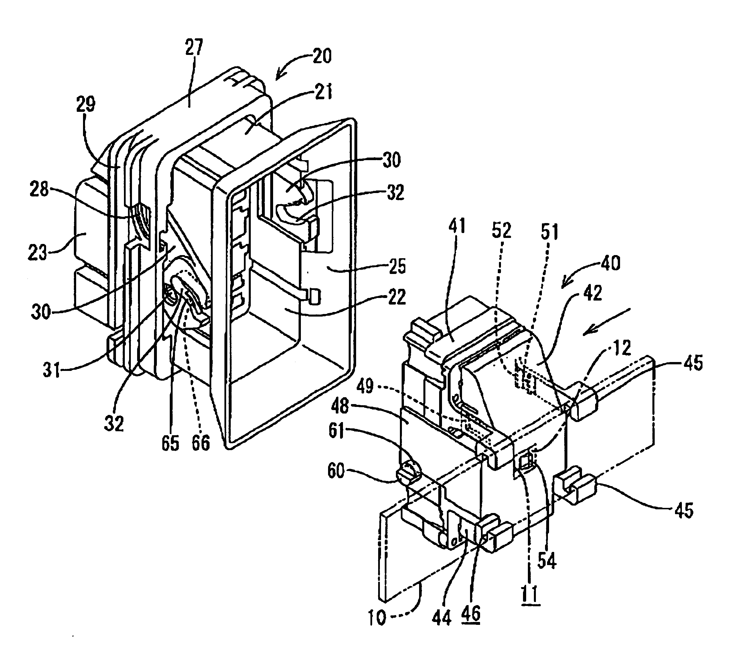
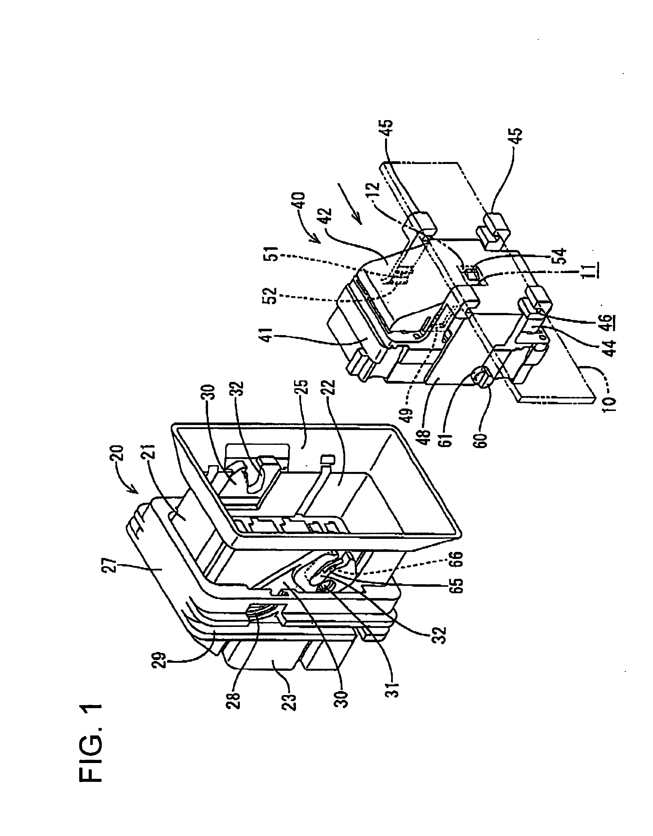
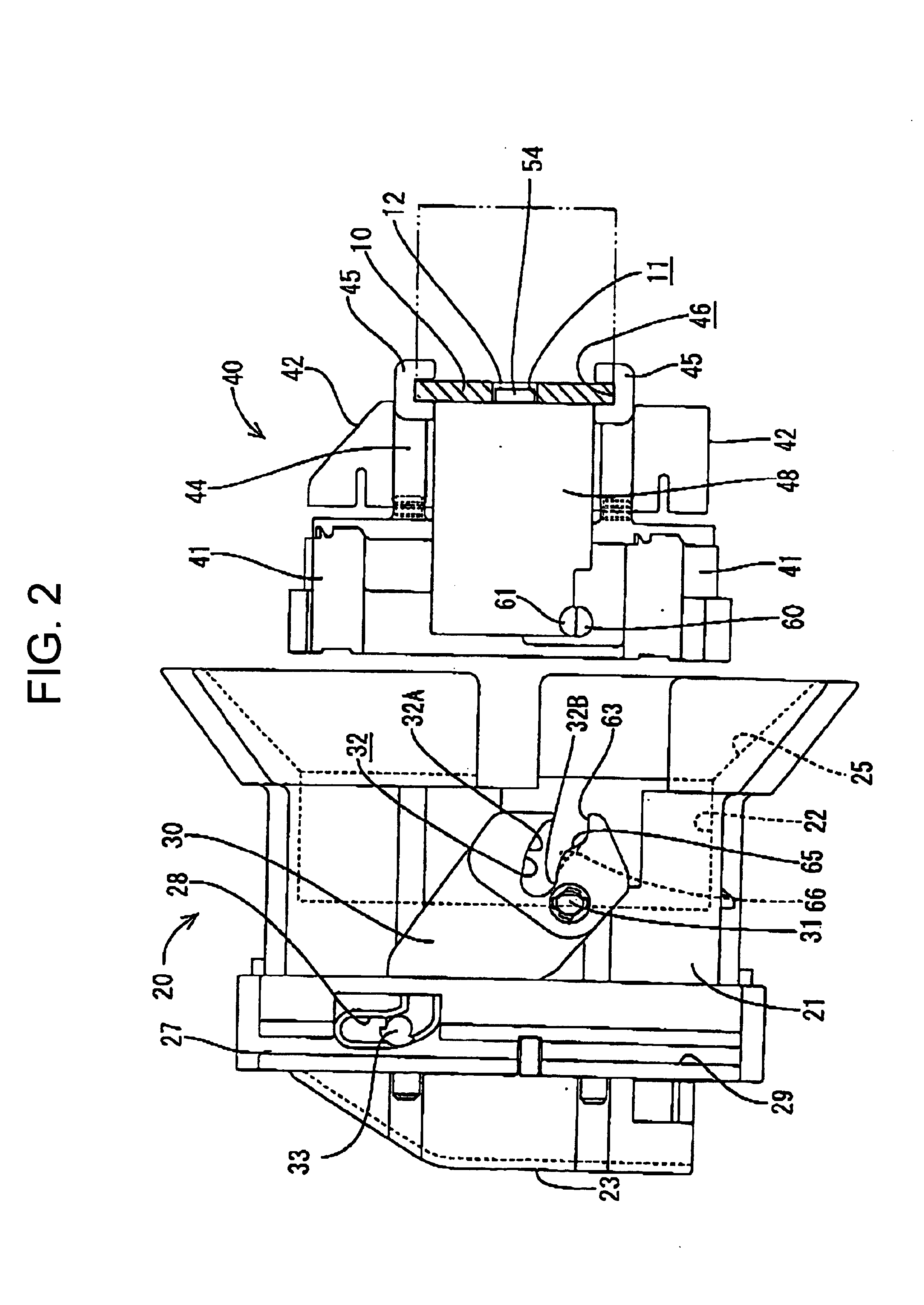
Hereinafter, an embodiment is described in which the present invention is applied to a waiting-type connector. As shown in FIGS. 1 and 2, a movable-side connector 20 is mounted on a module of an automotive vehicle such as an instrument panel, whereas a waiting-side connector 40 is mounted on a body via a bracket. As the module is assembled with the body, the movable-side connector 20 is connected with the waiting-side connector 40.

In the following description, sides of the two connectors 20, 40 to be connected are referred to as front side.

The movable-side connector 20 is a male connector and constructed such that male terminals (not shown) are inserted from behind to be accommodated into a male housing 21 formed with a rectangular and forward-opening receptacle 22, and a wire cover 23 is mounted on the rear surface of the male housing 21 to guide and draw out ...


PUM


Abstract

In a waiting-side connector 40, a cover 42 is detachably mounted on the rear surface of a female housing 41. Leg pieces 44 projecting from the female housing 41 are formed with guide rails 45 to define an insertion path 46 for a bracket 10. A lock protrusion 54 is formed on the rear surface of the cover 42, whereas a lock hole 11 is formed in the bracket 10. Independent follower pins 60, 61 are provided on the female housing 41 and the cover 42. In an area of a cam groove 32 of each lever 30 of a movable-side connector 20 corresponding to a final stage of a separating operation, cam surfaces 65, 66 for individually pushing the follower pins 60, 61 are formed such that the cover 42 is less separated than the female housing 41.

Description

BACKGROUND OF THE INVENTION1. Field of the InventionThe present invention relates to a bracket-mounted connector.2. Description of the Related ArtIn the case of assembling a module such as an instrument panel with a body in an automotive vehicle, a movable-side connector provided on the module is connected with a waiting-side connector mounted on the body as the module is assembled in order to reduce the number of operation steps for the assembling.The waiting-side connector is mounted on the body via a bracket. Specifically, the plate-shaped bracket projects from the body, whereas a rail-shaped insertion path is formed on an outer surface of the connector housing. When the bracket is inserted into the insertion path up to a specified position, a lock projection provided on the insertion path is fitted into and engaged with a lock hole formed in the bracket to mount the waiting-side connector so as not to come off.This type of the bracket-mounted connector is disclosed in JP-UM-A-1-...

Claims


Application Information

Patent Timeline
Patent Type & Authority Patents(United States)
IPC IPC(8): H01R13/629H01R13/502H01R13/506H01R13/73
CPCH01R13/62972H01R13/506H01R13/62938
Inventor OSAWA, HIROKIMIZOGUCHI, TOMOHISA
Owner SUMITOMO WIRING SYST LTD
Why Eureka
Try Eureka