Quick detachable and adjustable magnetic seat for sleeve

a magnetic seat and adjustable technology, applied in the field of magnetic seats, can solve the problems of inability to disassemble the combination of components, waste of resources, etc., and achieve the effect of efficient installation or removal, and preventing waste or resour

Active Publication Date: 2019-04-02
HU BOBBY
View PDF12 Cites 3 Cited by
  • Summary
  • Abstract
  • Description
  • Claims
  • Application Information

AI Technical Summary

Benefits of technology

[0007]For improving the issues above, a quick detachable and adjustable magnet seat for sleeve is disclosed for achieving an efficiently detaching the adjustable magnet seat from the sleeve when the sleeve is damaged or broken. Accordingly, the adjustable magnet seat is not necessarily discarded together with the damaged sleeve.
[0011]Preferably, when the adjustable magnetic seat is installed in the sleeve, the adjustable magnetic seat is axially pushed toward one end of the sleeve, so as to be efficiently engaged with the sleeve. When the adjustable magnetic seat is to be removed from the sleeve, the adjustable magnetic seat is axially pushed toward the other end of the sleeve, so as to be efficiently detached from the sleeve.
[0015]Preferably, the magnetic device includes a first axle member and a magnet. The magnet is disposed on one end of the first axle member for providing a magnetism. The detachable positioning device includes a second axle member on where the connecting end is formed. The connecting end of the second axle member is slidably disposed on the second end of the magnetic device. The resilient quick detach device is disposed on the other end of the second axle member away from the connecting end. The first axle member is provided with a first limit portion, and the second axle member is provided with a second limit portion. When the spring moves the magnetic device back to the original position, the first limit portion and the second limit portion prevent the spring from detaching the magnetic device from the detachable positioning device.
[0018]Preferably, an outer wall of the second axle member is further provided with a third limit portion, and the inner side of the sliding seat is provided with a fourth limit portion. The third and fourth limit portions conduct a blocking function, so as to prevent the sliding seat from detaching from the second axle member toward the resilient quick detach device.
[0023]With such configuration, the adjustable magnetic seat of the present invention is allowed to be efficiently installed in or removed from the sleeve, such that when the sleeve is damaged or broken, the user is able to efficiently remove the adjustable magnetic seat from the sleeve and subsequently applied the adjustable magnetic seat to a new sleeve. Therefore, the adjustable magnetic seat is not necessarily discarded with the damaged sleeve, thus preventing a waste or resource and saving the cost of purchasing a replacement of the whole assembly.

Problems solved by technology

However, once the magnetic device 14 and the fix device are combined into the main body 11, the combination thereof is unable to be disassembled.
As a result, the whole damaged driving tool 10 shall be discarded together with the inner assemblies, causing a waste of resource.

Method used


Image

  • Quick detachable and adjustable magnetic seat for sleeve
  • Quick detachable and adjustable magnetic seat for sleeve
  • Quick detachable and adjustable magnetic seat for sleeve

Examples


first embodiment

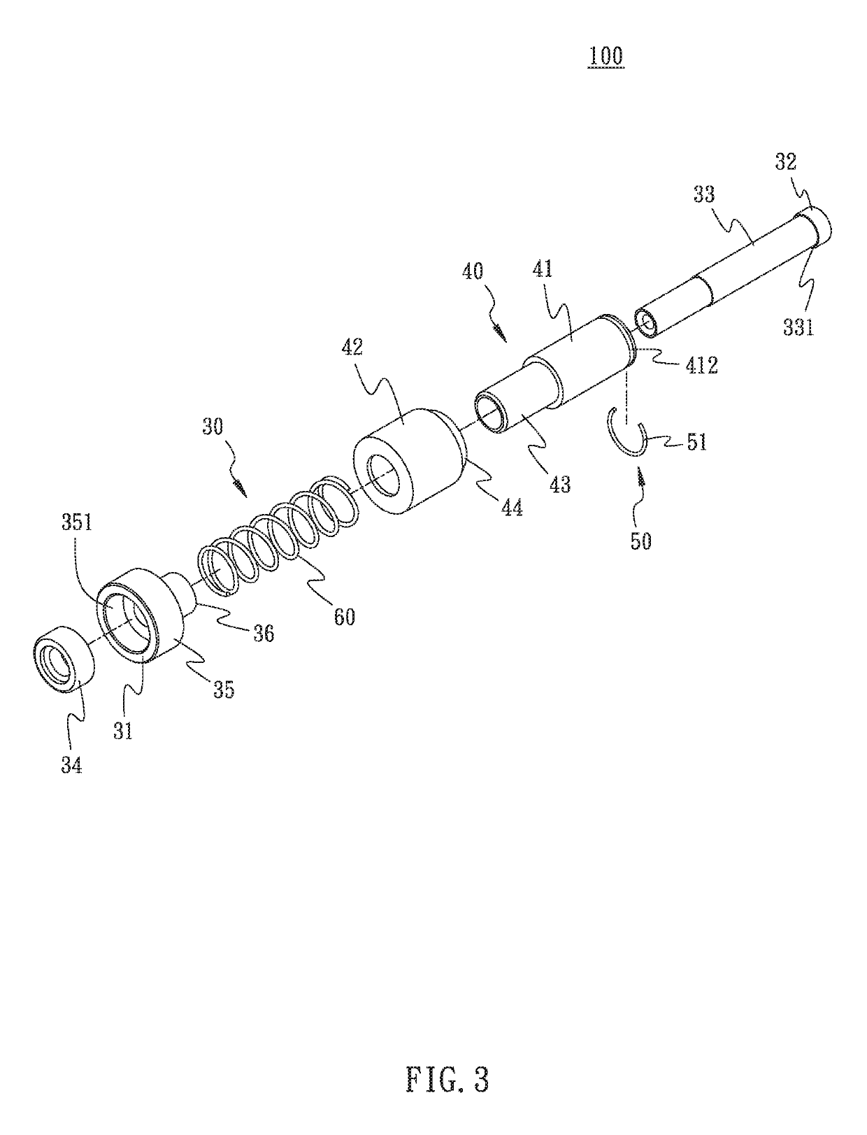
[0036]Referring to FIG. 3 to FIG. 9 illustrating the present invention, an adjustable magnetic seat 100 capable of being efficiently installed in or removed from a sleeve 200 comprises a magnetic device 30 and a detachable positioning device 40.

[0037]The magnetic device 30 includes a first end 31 and a second end 32, wherein the first end 31 is magnetic. In an embodiment of the present invention, the magnetic device 30 is provided with a first axle member 33 and a magnet 34, wherein the magnet 34 is disposed on one end of the first axle member 33 for providing the magnetism. The second end 32 is disposed on the other end of the first axle member 33 away from the magnet 34. Also, the magnetic device 30 further includes a bear seat 35. The bear seat 35 is provided with a containing bore 351 for containing the magnet 34, such that the bear seat 35 and the magnet 34 are disposed on the first axle member 33, whereby the bear seat 35 is prevented from detaching from the end of the first a...

second embodiment

[0048]Referring to FIG. 10, the present invention is illustrated. The resilient engage member of the resilient quick detach device 50 is integrally formed in a hook portion 52 which is disposed on one end of the detachable positioning device 40 away from the connecting end 43. The hook portion 52 defines the second outer diameter D2, wherein the two distal ends of the second outer diameter D2 are located at the outer periphery of the hook portion 52. Through the elastic deformation of the hook portion 52 and through the installation process from FIG. 6 to FIG. 8, the adjustable magnetic seat 100 is efficiently installed in or removed from the sleeve 200.

third embodiment

[0049]Referring to FIG. 11, the present invention is illustrated. The resilient engage member of the resilient quick detach device 50 includes a ball member 53 and a resilient member 54. In the embodiment, two ball members 53 and two resilient members 54 are provided and transversely disposed on two lateral sides on one end of the detachable positioning device 40 away from the connecting end 43. In other words, each resilient member 54 and the corresponding ball member 53 are orderly embedded in a radial groove 414 formed on one lateral side of the second axle member 41. Further, in this embodiment, the two distal ends of the second outer diameter D2 are located on the outer periphery of the two ball members 53. Also, the second end 32 of the first axle member 33 of the magnetic device 30 refers to a resilient tenon member 37, such that the first axle member 33 is allowed to pass through the connecting end 43 of the second axle member 41, and subsequently positioned due to the limit...


PUM

PropertyMeasurementUnit
magneticaaaaaaaaaa
outer diameteraaaaaaaaaa
lengthaaaaaaaaaa

Abstract

A quick detachable and adjustable magnetic seat for sleeve includes a magnetic device and a detachable positioning device. The magnetic device includes a first end and a second end. The first end is magnetic. The detachable positioning device includes a connecting end slidably disposed on the second end of the magnetic device, such that the magnetic device axially slides against the detachable positioning device. The detachable positioning device further includes a resilient quick detach device disposed on one end of the detachable positioning device away from the connecting end, whereby the detachable positioning device is removably disposed in a sleeve. Therefore, when the sleeve is damaged or broken, the adjustable magnetic seat is efficiently removed from the sleeve and re-installed in a new sleeve replacement.

Description

BACKGROUND OF THE INVENTION[0001]1. Field of the Invention[0002]The present invention relates to magnetic seats, and more particularly, to a quick detachable and adjustable magnetic seat for sleeve.[0003]2. Description of the Related Art[0004]A conventional resiliently movable magnetic device for sleeve is developed for meeting convenience of usage, so as to move a target object during the movement of the sleeve. Also, the target object is thereby able to be removed efficiently.[0005]As shown by FIG. 1, a conventional magnetic driving tool 10 comprises a main body 11, a fix device including a first fixing member 12 and a second fixing member 13, and a magnetic device 14. The main body 11 is provided with a driving end 11a and an operating end 11b disposed in opposite to the driving end 11a. The first fixing member 12 is engaged with one side of a protrusion 15 inside the main body 11 facing the driving end 11a, while the second fixing member 13 is engaged with the other side of the ...

Claims


Application Information

Patent Timeline
Patent Type & Authority Patents(United States)
IPC IPC(8): B23B31/00B23B31/28B25B13/06B25B23/00B25B23/12H01R11/30H01F7/02
CPCB23B31/003B23B31/28B25B13/06B25B23/0035B25B23/12Y10T279/3481B23B2231/04H01F7/0205H01R11/30Y10T279/3406
Inventor HU, BOBBY
Owner HU BOBBY
Why Eureka
Try Eureka