Connector, a connector assembly, a jig, and a method for withdrawing a terminal in a connector

a technology of connectors and jigs, applied in the direction of securing/insulating coupling contact members, coupling device connections, electrical devices, etc., can solve the problem that the retainer rib cannot fit into the accommodating groove, and achieve the effect of improving the locking force and facilitating the lockdown of the terminal fitting

Active Publication Date: 2005-01-27
SUMITOMO WIRING SYST LTD
View PDF6 Cites 2 Cited by
  • Summary
  • Abstract
  • Description
  • Claims
  • Application Information

AI Technical Summary

Benefits of technology

[0022] The terminal fitting can be disengaged from the lock by inserting the disengaging portion of the jig into the jig insertion space from the front and substantially along the insertion and withdrawal directions. A dimension of the jig insertion space along a deforming direction of the lock is less than a dimension of the disengaging portion along the deforming direction of the lock. Additionally, the difference between the dimension of the jig insertion space and the dimension of the disengaging portion substantially equals a displacement of the lock necessary to cancel the locked state of the terminal fitting. Thus, insertion of the disengaging portion to a specified depth resiliently deforms the lock until the locked state of the terminal fitting is canceled. The disengaging portion then engages the pushable projection that projects from the terminal fitting and pushes unlocked terminal fitting back. Accordingly, one disengaging portion resiliently deforms the lock and moves the female terminal fitting back. Thus, the jig is simple and the female terminal fitting can be detached more efficiently than with the prior art jig where these two functions are performed by two special parts.
[0023] An introducing part of the lock for introducing the disengaging portion preferably has a slanted guiding surface that is inclined to gradually decrease the dimension of the jig insertion space along the deforming direction of the lock toward the back. Thus, the disengaging portion can be inserted more smoothly into the jig insertion space.
[0024] The pushable projection preferably is widened so that a projecting distance thereof increases gradually toward the back, and a slanted guiding surface is formed on an outer surface of the pushable projection for guiding the disengaging portion in an unlocking direction of the lock by sliding in contact with the disengaging portion. Thus, the locked state of the terminal fitting by the lock can be canceled more securely.
[0025] The pushable projection preferably is engageable with the lock for locking the terminal fitting. Thus, a locking force for locking the terminal fitting in the locked state can be improved.

Problems solved by technology

In this situation, the retainer rib projects out beyond the housing rib and hence the retainer rib cannot fit into the accommodating groove.

Method used


Image

  • Connector, a connector assembly, a jig, and a method for withdrawing a terminal in a connector
  • Connector, a connector assembly, a jig, and a method for withdrawing a terminal in a connector
  • Connector, a connector assembly, a jig, and a method for withdrawing a terminal in a connector

Examples


Embodiment Construction

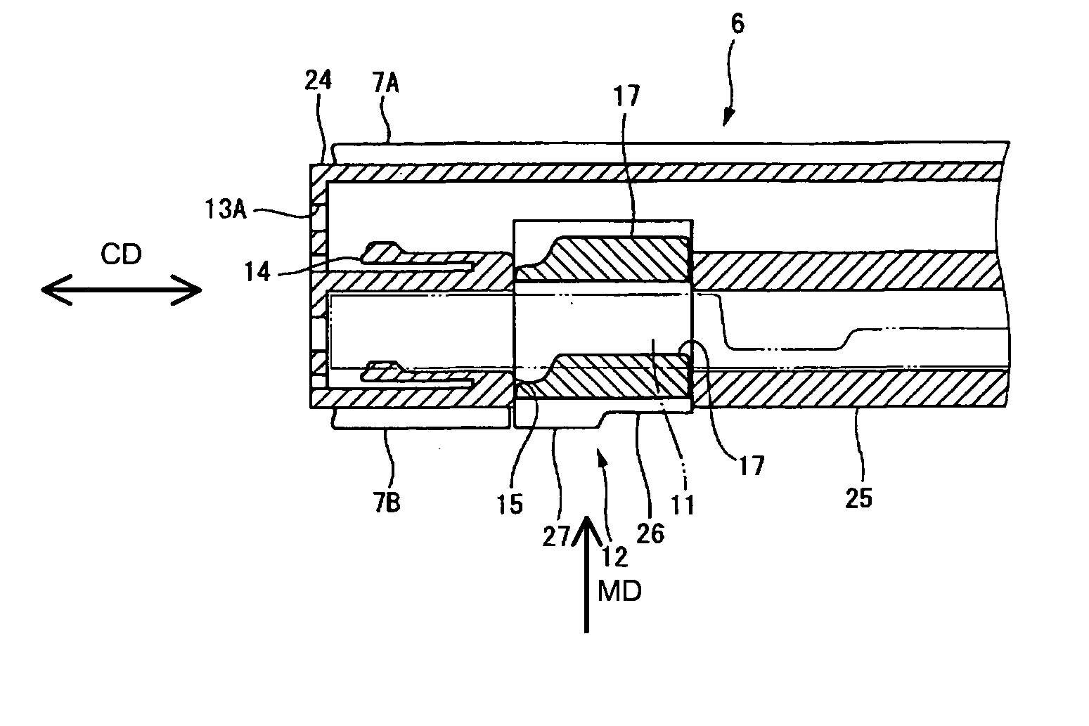
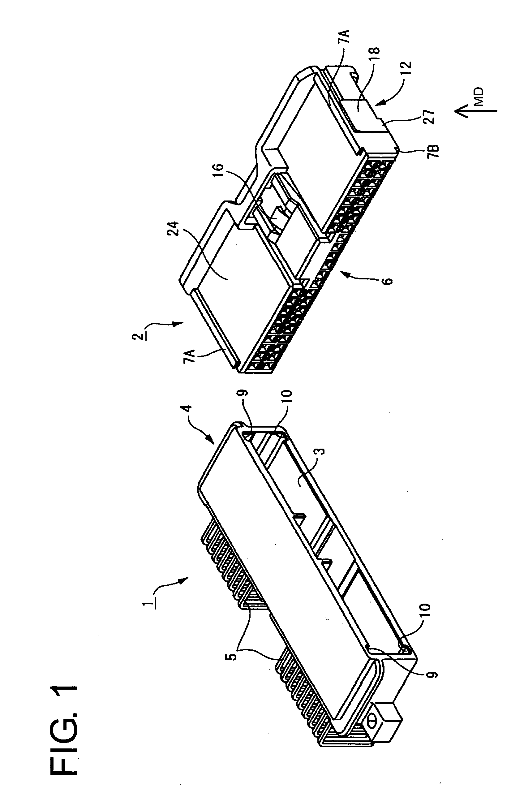
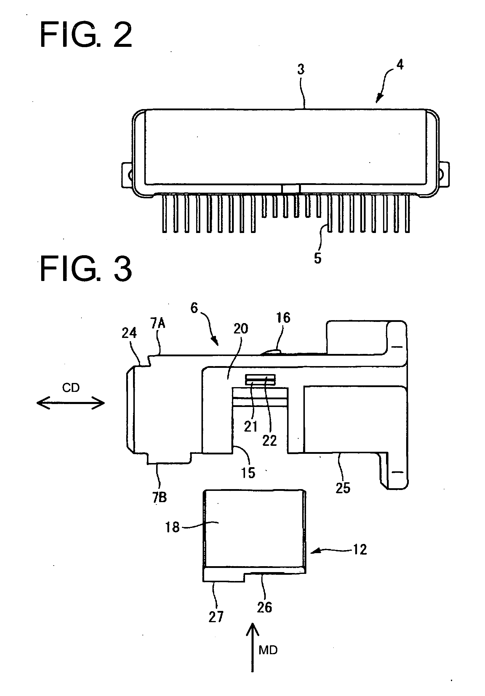
[0050] A first embodiment of the invention is described with reference to FIGS. 1 to 11. FIG. 1 shows male and female connectors 1, 2 connectable with each other along a connecting direction CD. In the following description, sides (those shown in FIG. 1) of the two connectors 1, 2 to be connected are referred to as the front sides. The male connector 1 shown has a male housing 4 formed with a receptacle 3 and male terminal fittings 5 made of electrically conductive members.

[0051] Each male terminal fitting 5 is a substantially rectangular column with an intermediate portion inserted through and fixed in a rear wall 4a of the male housing 4 (see also FIG. 9). Each male terminal fitting 5 has a coupling end 5A and fixed end 5B. The coupling end 5A is accommodated in the receptacle 3. The fixed end 5B extends back from the rear wall 4A and is bent down substantially normal to the coupling end 5A. Although not shown, the male connector 1 is to be fixed to a plate, such as a printed cir...


PUM


Abstract

A connector includes a housing (130) with a cavity (131) and a lock (133) that is resiliently deformable along a deformation direction (DD). A terminal fitting (110) is insertable into and withdrawable from the cavity (131) along inserting and withdrawing directions (IWD) and is configured to be locked by the lock (133). A jig (160) can be slid linearly into a jig insertion space (148) between the terminal fitting (110) and the lock (133) for disengaging the lock (133) from the terminal fitting (110).

Description

[0001] This application is a divisional of U.S. patent appl. Ser. No. 10 / 757,699, filed Jan. 14, 2004.BACKGROUND OF THE INVENTION [0002] 1. Field of the Invention [0003] The invention relates to a connector. Furthermore, the invention relates to a jig and a method for withdrawing a terminal in a connector. [0004] 2. Description of the Related Art [0005]FIG. 12 shows a male connector with a male housing 100 and female connector with a female housing 101. The male housing 100 has a receptacle 102 for accommodating the female housing 101. The female housing 101 has a retainer 103 for locking unillustrated terminal fittings. The retainer 103 can be mounted at a partial locking position, where the retainer 103 is assembled lightly with the female housing 101, and at a full locking position, where the retainer 103 is assembled deeply in the female housing 101 to lock the terminal fittings. [0006] Housing ribs 104A, 104B project up or down from opposite left and right ends of upper and low...

Claims


Application Information

Patent Timeline
Patent Type & Authority Applications(United States)
IPC IPC(8): H01R13/422H01R13/436
CPCH01R4/185H01R4/188H01R13/4223H01R43/22H01R13/6271H01R13/641H01R13/4362
Inventor AIHARA, TETSUYAOKAMOTO, MICHIAKI
Owner SUMITOMO WIRING SYST LTD
Why Eureka
Try Eureka