Valve device

A valve device, valve body technology, applied in the direction of valve device, lift valve, valve details, etc.

Inactive Publication Date: 2012-01-11
CHIYODA KUCHOKIKI
View PDF10 Cites 3 Cited by
  • Summary
  • Abstract
  • Description
  • Claims
  • Application Information

AI Technical Summary

Problems solved by technology

[0006] However, this does not solve all problems

Method used


Image

  • Valve device
  • Valve device
  • Valve device

Examples


Embodiment Construction

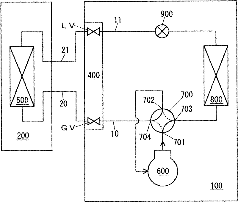
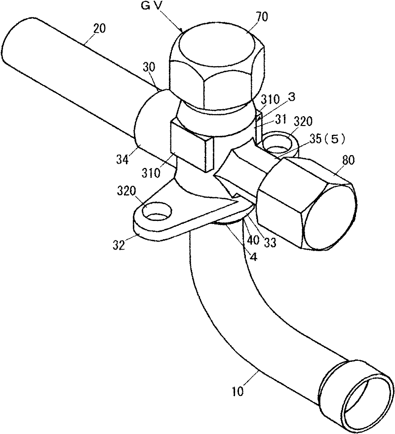
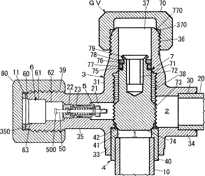
[0040] Such as figure 1 As shown, the valve device according to the present invention is applied to the gas side valve GV, which is used to connect the internal piping 10 on the gas side of the outdoor unit 100 (the internal piping 10 viewed from the outdoor unit 100) and The gas-side external piping 20 extending from the indoor unit 200 (the external piping 20 viewed from the outdoor unit 100 ) is connected together. A spool is not provided in the liquid-side valve LV for connecting the liquid-side internal piping 11 of the outdoor unit 100 and the liquid-side external piping 21 extending from the indoor unit 200 . However, it is also possible to apply the valve device of the present invention having a service port portion with a built-in valve core to the liquid side valve LV. The gas-side valve GV and the liquid-side valve LV are arranged and supported by the frame 400 of the outdoor unit 100 .

[0041] The indoor unit 200 includes an indoor heat exchanger 500 that serves...


PUM


Abstract

The invention provides a valve device, which can well maintain the sealing performance of the valve core part even if a relatively high-pressure refrigerant, such as the CO2 type refrigerant is adopted, and further make an inflating flexible pipe connected with a vacuum pump well removed from a maintenance opening part in a way that the O ring of a pressure bar part will not break. The maintenance opening part (35) is provided with a pressure bar receiving hole (6) having a preset depth and applied for installing and uninstalling the pressure bar part (9) with an O ring (90). The operating end part (500) of a central pin (50) of the valve core (5) is made to face the inner part of the pressure bar receiving hole (6). Meanwhile, in the sealing contact starting end side located inside the pressure bar receiving hole (6) and contacting with the O ring (90) of the pressure bar part (9), an internal-pressure relieving path (63) is equipped on a part where the pressure bar part (9) and the central pin (50) leave. The internal-pressure relieving path (63) allows the axial communication when the O ring (90) is clamped.

Description

technical field [0001] The present invention relates to a valve device for an air conditioner. The valve device is provided with a valve body having an inspection port with a built-in valve core (connection to a charge hose when performing inspection work such as vacuuming). end-connected part), the valve device uses a valve stem to open and close the refrigerant passage provided inside the valve body. Background technique [0002] In the past, generally, for this kind of valve device, as known in Patent Document 1, etc., an inspection port with a built-in valve core is integrally provided on one side of the valve body. When connecting to the pipe connection on the other side of the valve body, before lifting the valve stem to circulate the refrigerant indoors and outdoors, screw the connection end of the inflation hose connected to the vacuum pump into the outer circumference of the inspection port, and use the inflation The valve core pusher of the hose presses the core p...

Claims


Application Information

Patent Timeline
Patent Type & Authority Applications(China)
IPC IPC(8): F16K1/04F16K41/04F16K27/02F16K51/00
Inventor 泷川宪
Owner CHIYODA KUCHOKIKI
Why Eureka
Try Eureka