
Interruptible power supply module

a power supply module and power supply technology, applied in the field of interruptible power supply modules, can solve the problems of unrelenting electrical energy demand, affecting business operations, and affecting business operations, and achieve the effects of prolonged blackouts, extended outages, and scattered and widespread blackouts

Inactive Publication Date: 2005-04-12
SLEVA ASSOCS
View PDF26 Cites 128 Cited by
  • Summary
  • Abstract
  • Description
  • Claims
  • Application Information

AI Technical Summary

Benefits of technology

It is an advantage of the present invention that when a sustained power failure has occurred, the interruptible power module can be used to further extend the outage of the interruptible loads beyond the time the rest of the loads are brought up when power is restored. That is, the module can be used to extend the power failure associated with the interruptible loads for an additional 15 to 30 minutes (for example).
that when a sustained power failure has occurred, the interruptible power module can be used to further extend the outage of the interruptible loads beyond the time the rest of the loads are brought up when power is restored. That is, the module can be used to extend the power failure associated with the interruptible loads for an additional 15 to 30 minutes (for example).
During a situation such as underfrequency load shedding, this same advantage can be used to cut power to the interruptible loads to avoid the need for prolonged, scattered and widespread blackouts in the community.

Problems solved by technology

Increases in energy prices coupled with worsening pollution levels add to the problems associated with the unrelenting demand for electrical energy.
In many cases, un-announced blackouts (from an extreme over-demand) on the supply cause havoc within affected businesses, as well as within the residential community.
Pro-active “brownouts”, where the utility company schedules the brownouts in advance, provides some relief in terms of giving an advanced warning to the affected customers, but is still an inconvenience.

Method used


Image

  • Interruptible power supply module
  • Interruptible power supply module
  • Interruptible power supply module

Examples


Embodiment Construction

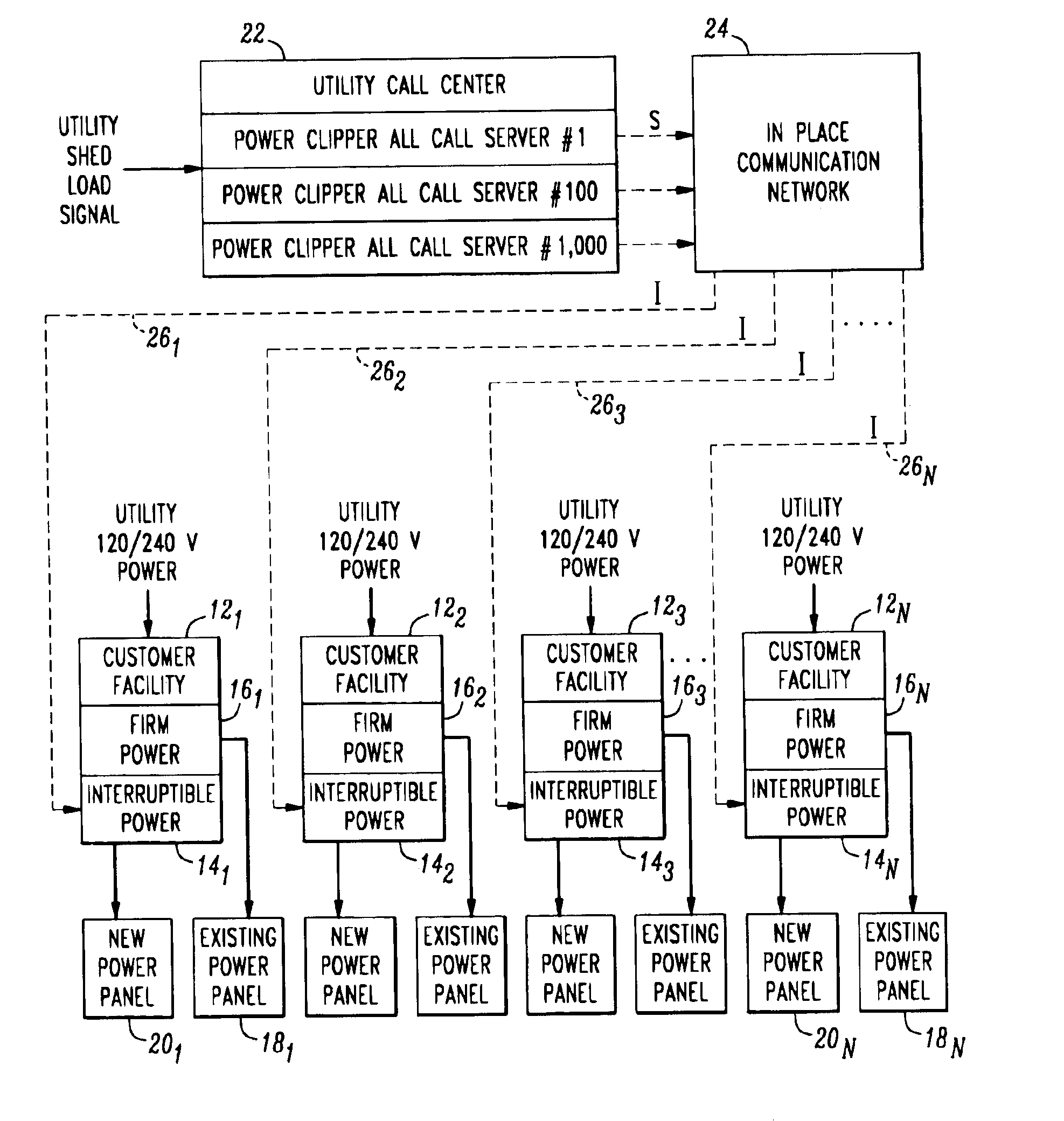
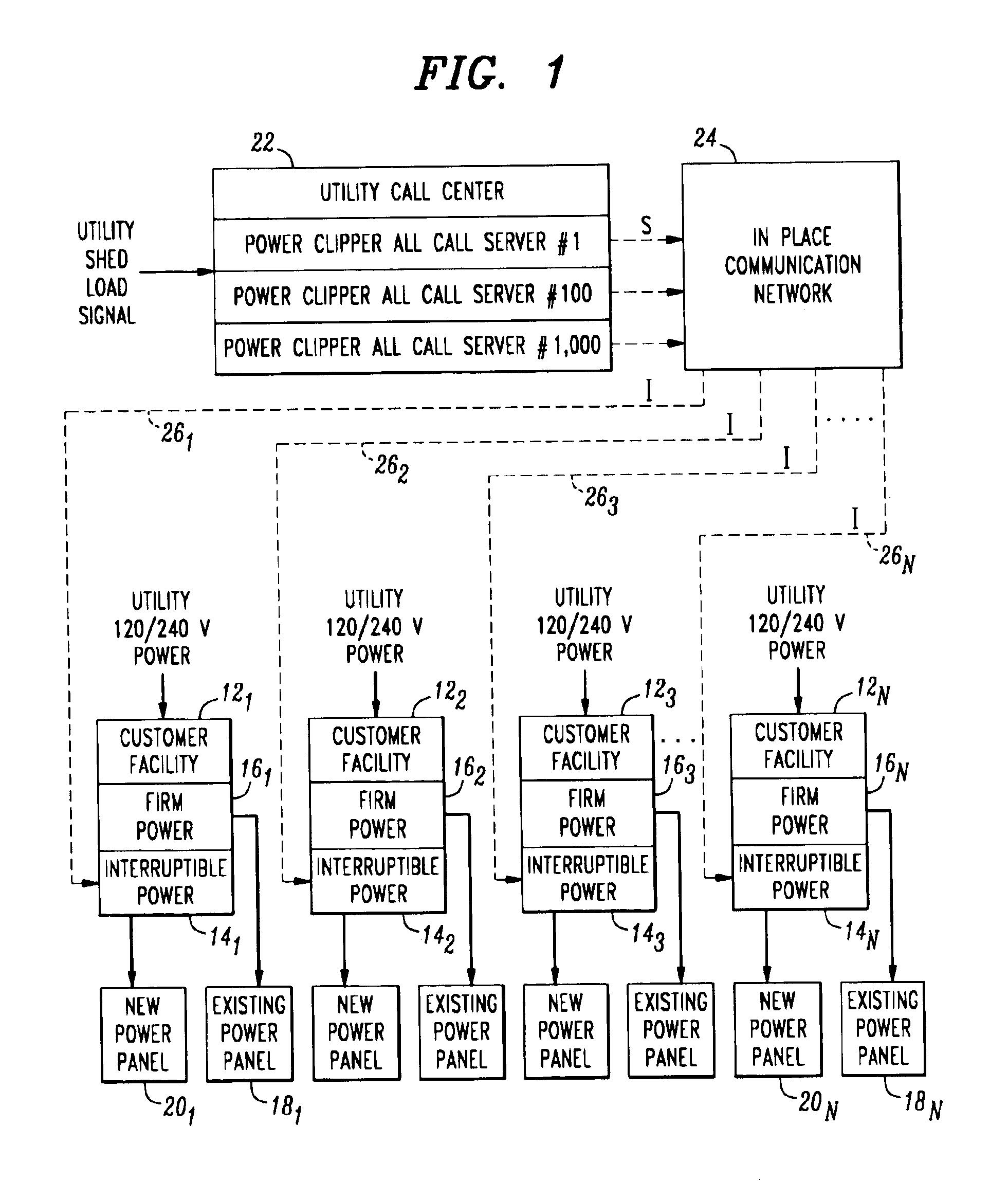
FIG. 1 illustrates an exemplary network arrangement 10 for deploying the interruptible power supply technique of the present invention. Included in this arrangement is a plurality of customers 121-12N, where each customer has selected certain loads within its premises that may be subject to “interruptible power”, these loads designated 141-14N, with the remaining loads defined as “firm power” and designated 161-16N. Each customer's existing power panel 181-18N may be associated with the “firm power” load, and a separate power panel 201-20N associated with the pre-selected “interruptible power” loads.

In accordance with the teachings of the present invention, a utility call center 22 is included in the arrangement and functions to react to changes in load conditions experienced by the power company and determine when the need arises to clip the load of power being distributed to customers 121-12N. When call center 22 is directed to shed load, it sends a control signal S to an element ...


PUM


Abstract

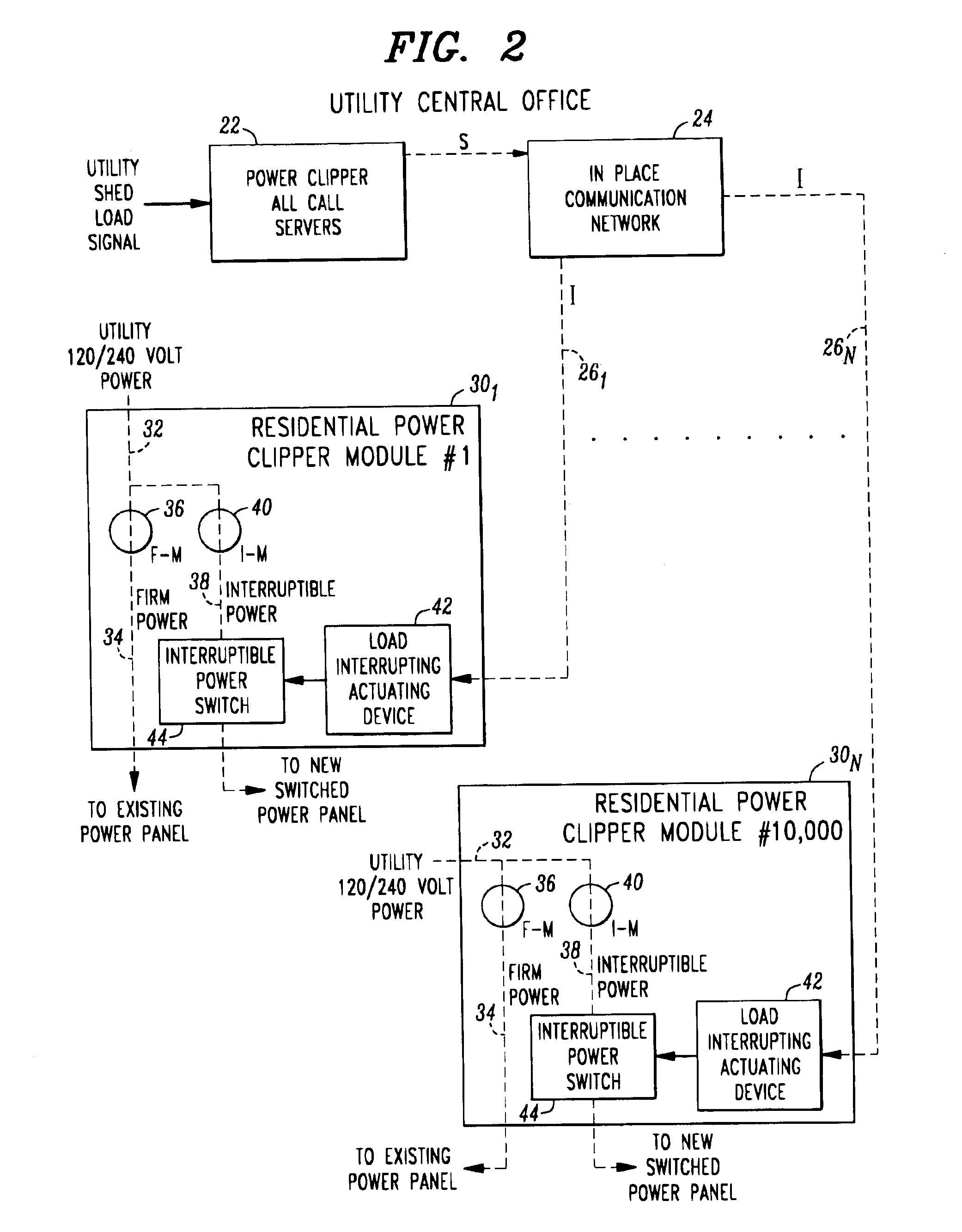
An interruptible power supply module, located at a customer's premise, functions to reduce the demand on a power utility company. As a power utility senses a critical power supply demand situation, it sends an “interrupt power” control signal through an alternative communications network (a telecommunications network, for example), to each subscribing customer. Upon receipt of the “interrupt” control signal, a switch is activated in the customer's interruptible power supply module to remove a pre-defined “interruptible” load for a predetermined period of time (perhaps not to exceed 15 minutes in any hour). The module may also be used to “gracefully” add interruptible loads back onto the system after a complete power outage.

Description

TECHNICAL FIELDThe present invention relates to an interruptible power supply module and, more particularly, to a customer-based module for designating certain loads as “interruptible” and thus capable of being turned off by the power company when necessary.BACKGROUND OF THE INVENTIONWith increasing regularity, electric power utility companies have initiated “black outs”, “brown outs”, and “rolling blackouts” to cope with a condition of too little available energy and too much demand. Increases in energy prices coupled with worsening pollution levels add to the problems associated with the unrelenting demand for electrical energy.In many cases, un-announced blackouts (from an extreme over-demand) on the supply cause havoc within affected businesses, as well as within the residential community. Pro-active “brownouts”, where the utility company schedules the brownouts in advance, provides some relief in terms of giving an advanced warning to the affected customers, but is still an inc...

Claims


Application Information

Patent Timeline
IPC IPC(8): H02J13/00H02J3/12H02J3/14
CPCH02J13/0006H02J3/14H02J13/00034Y04S20/222Y02B70/3225H02J2310/60H02J13/00002Y04S10/30Y02E60/00
Inventor SLEVA, ANTHONY FRANCIS
Owner SLEVA ASSOCS
Learn More