
Thin-film display mounting structure

a technology of mounting structure and thin film, which is applied in the direction of identification means, roofs, instruments, etc., can solve the problems of not being able to remove the display holder from the car, and being unable to destruct or remove a part of the car

Inactive Publication Date: 2005-04-19
HEXA CHAIN
View PDF6 Cites 13 Cited by
  • Summary
  • Abstract
  • Description
  • Claims
  • Application Information

AI Technical Summary

Benefits of technology

[0006]To achieve these and other objects of the present invention, the thin-film display mounting structure comprises a thin-film display, a pivot shaft fastened pivotally with a back side of the thin-film display, and at least one hook fastened to the pivot shaft for hanging the thin-film display on a support member, which can be a sun visor inside a car, or a headrest cover with back hook plates for a front seat in a car. A stand may be used and mounted with a rigid rack for the hanging of the hooks, for enabling the thin-film display to be supported on a bearing flange at the rigid rack.

Problems solved by technology

When installing the display holder, it may be necessary to destruct or remove a part of the car.
After installation of the display holder, the display holder cannot be removed from the car for supporting the display device on a support member outside the car.

Method used


Image

  • Thin-film display mounting structure
  • Thin-film display mounting structure
  • Thin-film display mounting structure

Examples


Embodiment Construction

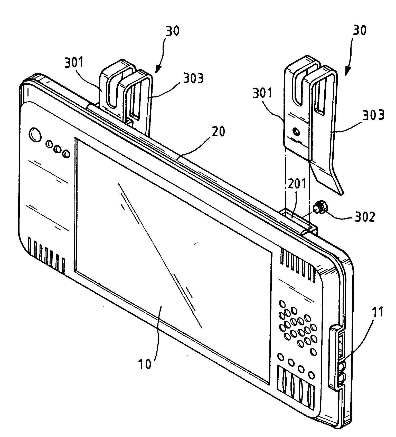
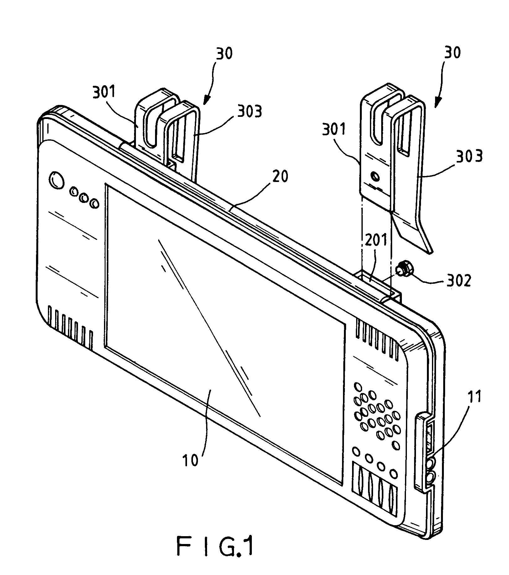
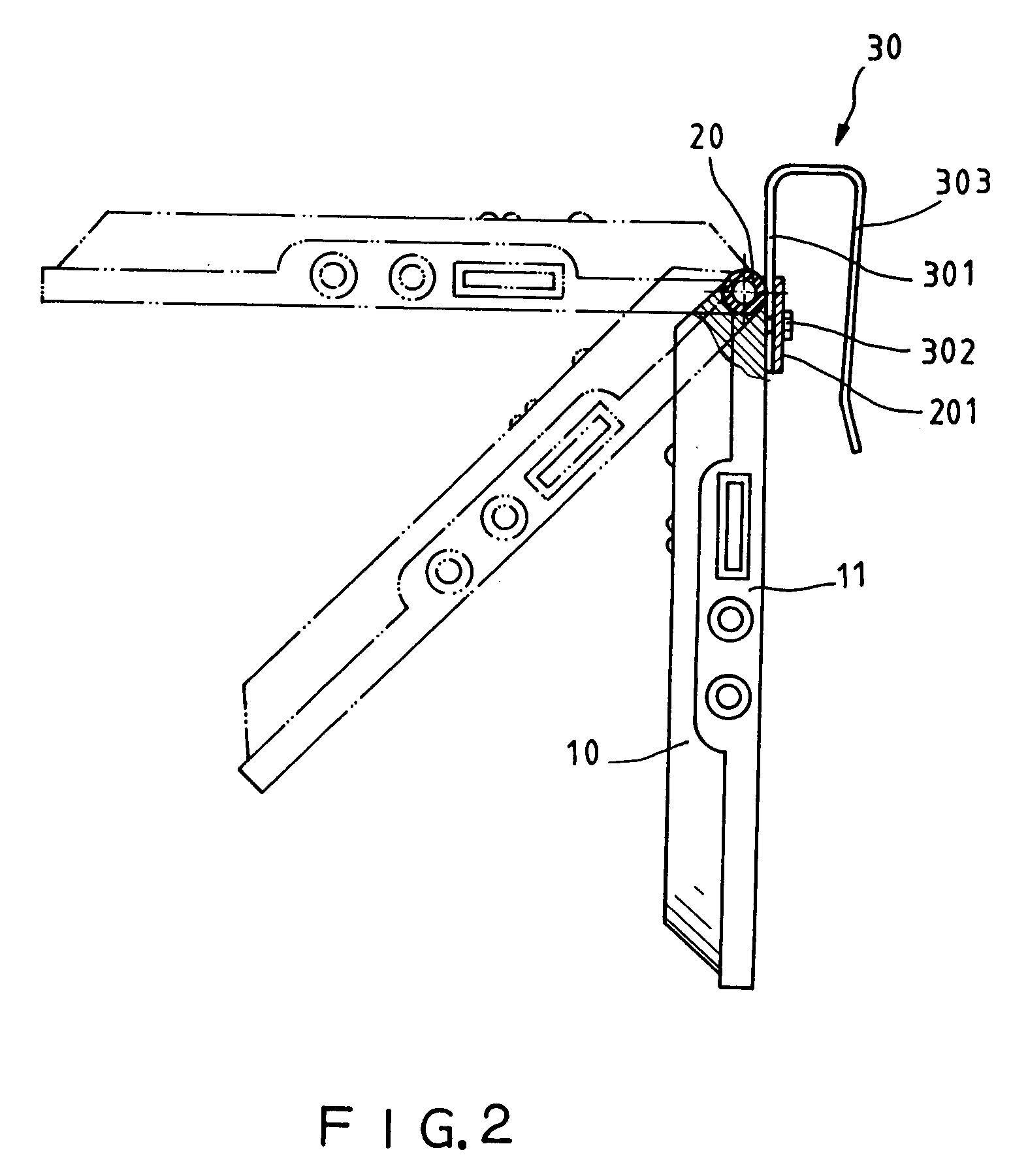
[0017]Referring to FIGS. 1 and 2, a thin-film display 10 is shown having a pivot shaft 20 pivotally disposed at the back near the top. The pivot shaft 20 has two mounting lugs 201 symmetrically disposed near the ends. Two hooks 30 are fastened to the pivot shaft 20 for mounting. The hooks 30 each have a relatively shorter rear mounting portion 301 and a relatively longer front clamping portion 303. The rear mounting portions 301 of the hooks 30 are respectively fastened to the mounting lugs 201 of the pivot shaft 20 by a respective screw 302. When assembled, the thin-film display 10 can be turned about the pivot shaft 20 relative to the hooks 30 to the desired angle (see FIG. 2).

[0018]Referring to FIGS. 3–6, by means of the hooks 30, the thin-film display 10 can be directly hung on the sun visor 40 in front of the mirror 41 at the sun visor 40 inside the car (see FIGS. 3, 4, and 6), or hung on hook plates 43 at the back of the cover 42 of the headrest 44 of one front seat of the car...


PUM


Abstract

A thin-film display mounting structure includes a thin-film display, a pivot shaft fastened pivotally with the back side of the thin-film display near the top, and two hooks fixedly fastened to the pivot shaft for hanging the thin-film display on a sun visor inside a car, or hook plates at the back of the cover of the headrest of one front seat of a car.

Description

BACKGROUND OF THE INVENTION[0001]1. Field of the Invention[0002]The present invention relates to thin-film displays and, more specifically, to a thin-film display mounting structure, which enables a thin-film display to be angularly adjustably hung on any of a variety of support members.[0003]2. Description of the Related Art[0004]Modern motor vehicles are commonly equipped with a display device for output of video signal from, for example, a DVD player, video game machine, global positioning system, satellite navigator, etc. When wishing to install a display device in a car without display device, a display holder or the like may have to be fastened to a part inside the car to hold the display device. When installing the display holder, it may be necessary to destruct or remove a part of the car. After installation of the display holder, the display holder cannot be removed from the car for supporting the display device on a support member outside the car.SUMMARY OF THE INVENTION[0...

Claims


Application Information

Patent Timeline
Patent Type & Authority Patents(United States)
IPC IPC(8): B60N2/48B60R11/02G09F21/00G09F21/04G09F9/35B60R11/00B60N2/879
CPCB60N2/4876B60R11/0235G09F9/35G09F21/04B60R2011/0017Y10S248/921B60R2011/0035B60N2/879G09F21/049
Inventor HUANG, FU-RUEICHEN, KO-CHI
Owner HEXA CHAIN
Learn More