Pulley

a technology of a pulley and a handle is applied in the field of pulleys, which can solve the problems of large forces, insufficient radial resilience, and insufficient radial resilience to absorb forces

Inactive Publication Date: 2005-04-19
WILHELM KAECHELE ELASTOMERTECHN
View PDF17 Cites 30 Cited by
  • Summary
  • Abstract
  • Description
  • Claims
  • Application Information

AI Technical Summary

Benefits of technology

[0021]The simplest way to achieve the clamping effect is to split the clamping device into two rings, the thickness of which varies in the axial direction. In the simplest case, each of the rings has an outer frustoconical form and a frustoconical bore, the cones defining these surfaces being in opposition. When the two rings of the clamping device are assembled

Problems solved by technology

However, it has been found here that, in such pulleys, the radial resilience is not sufficient to absorb forces which are produced owing to the fact that a clamping socket acting on the rope runs over the pulley.
This results in considerable forces, since the change in the distance between the center of the pulley and the core of the rop

Method used


Image

  • Pulley
  • Pulley
  • Pulley

Examples


Embodiment Construction

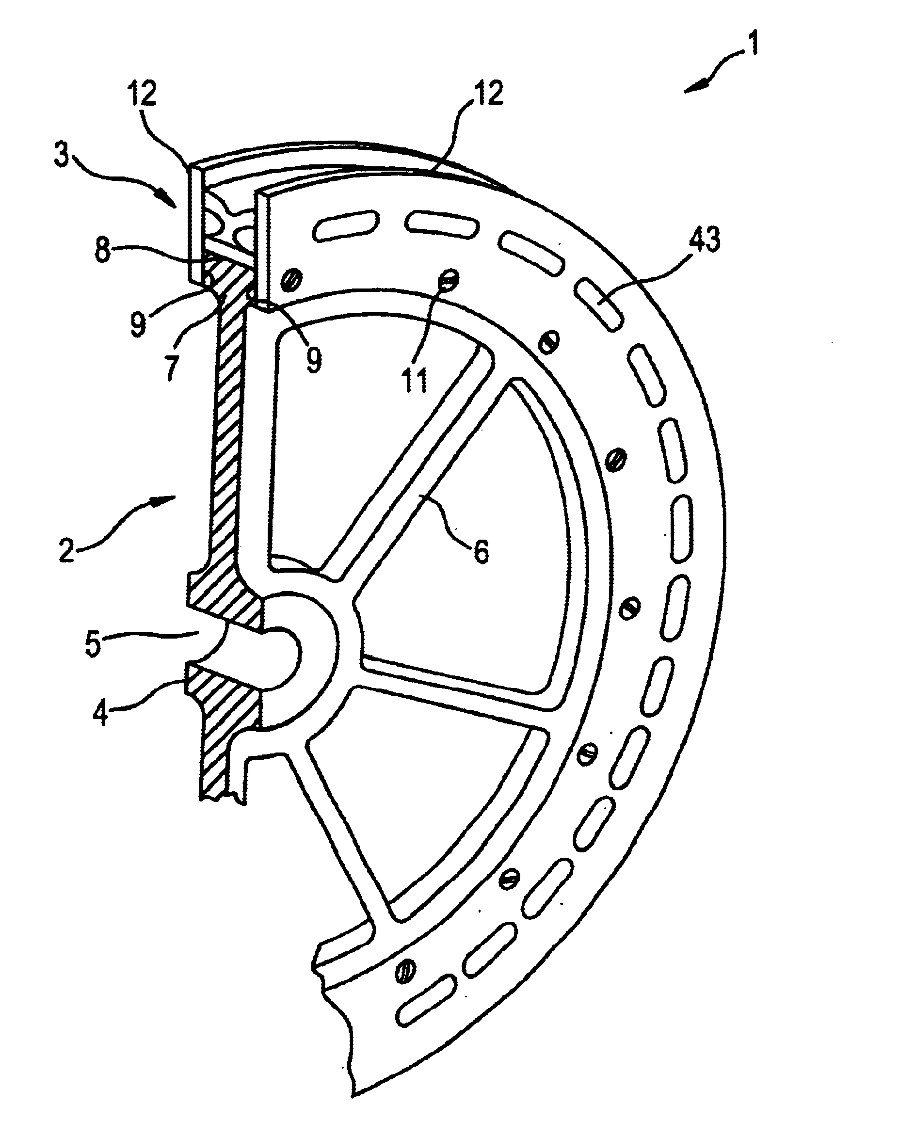
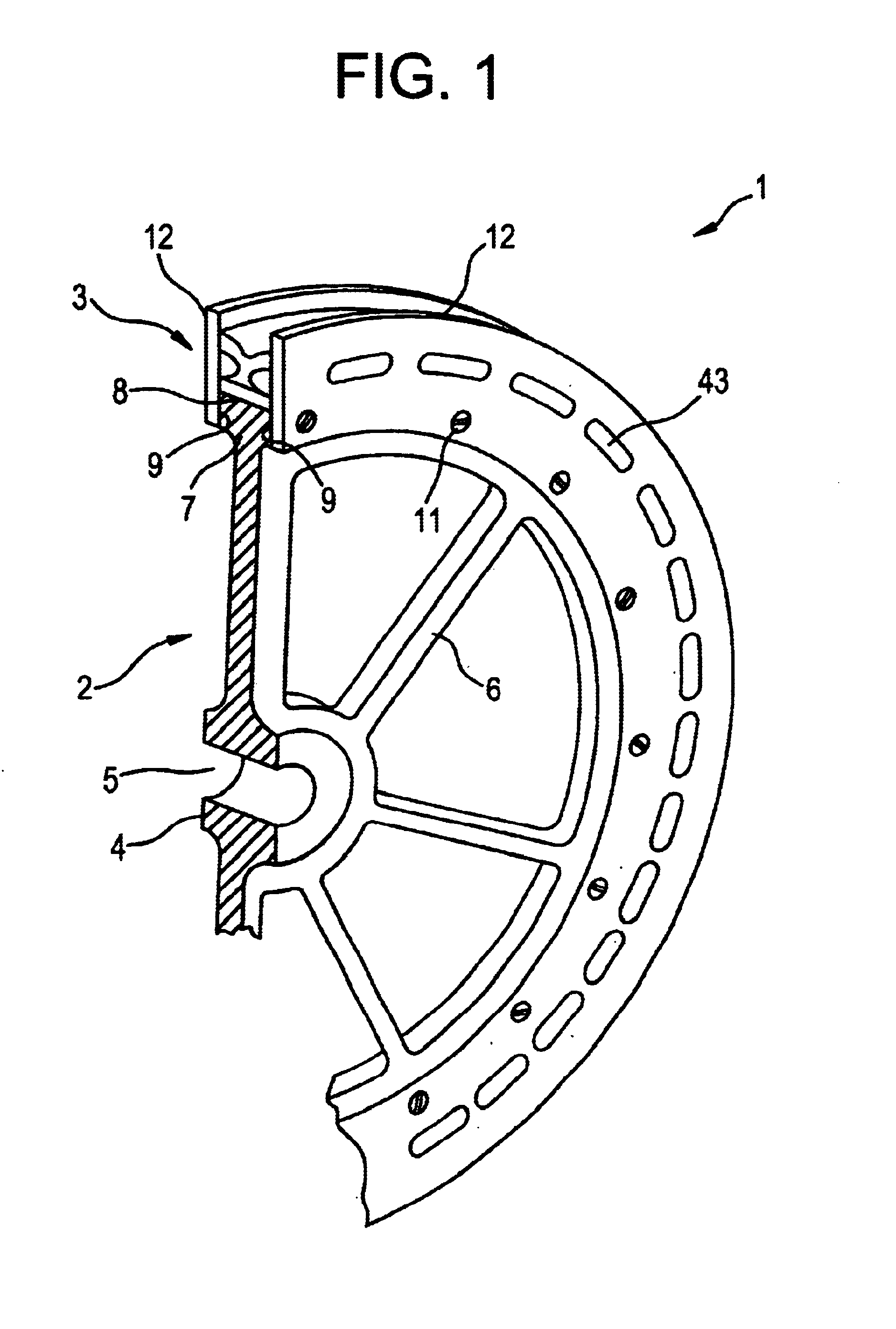
[0027]A pulley 1 for aerial tramways is illustrated in FIG. 1 in a perspective truncated representation.

[0028]The pulley 1 has a pulley body 2 and a tire 3 fastened to the latter. The pulley body 2 is a one-piece casting, which forms a central, approximately cylindrical hub 4 with a continuous bearing bore 5. A plurality of spokes 6, which are designed as compression spokes, emanate radially outward from the hub 4 to an outer pulley ring 7, which is connected in one piece with the hub 4 via the compression spokes 6. The pulley ring 7 forms a cylindrical seating face 8 for the tire 3. The cylindrical seating face 8 is concentric to the bearing bore 5.

[0029]The pulley ring 7 is defined in the axial direction by two flank faces 9, which are essentially parallel to one another and, starting from the cylindrical seating face 8, extend by a short distance in the radial direction toward the hub 4.

[0030]In the exemplary embodiment shown, the flank faces 9 are annular flat faces which are pa...


PUM


Abstract

A pulley consists of a pulley basic body which has a cylindrical outer circumferential surface. Sitting on this cylindrical outer circumferential surface is a tire which is of sandwich-like design with regard to its radial extent. This results in a plurality of rings concentric to one another. The ring which is furthest on the inside in the radial direction and the ring which is furthest on the outside in the radial direction are in each case elastomeric rings, whereas a reinforcing ring is located between them. The elastomeric outer ring is harder than the elastomeric inner ring, so that a very abrasion-resistant surface is achieved, over which the rope runs, whereas the elastomeric inner ring provides for adequate resilience. The reinforcing ring is provided in order to distribute the rope load as uniformly as possible over the elastomeric inner ring.

Description

BACKGROUND OF THE INVENTION[0001]Pulleys are required for guiding and supporting ropes in aerial tramways for the transport of materials and passengers. As shown by EP-A-O 185 531, such pulleys consist of a basic body which has a wheel hub with which the pulley is mounted so as to be rotatable on a fixed spindle. Emanating from the wheel hub are spokes, which are designed as compression spokes and connect the wheel hub to an outer ring of the basic body. This outer ring forms a cylindrical outer circumferential surface, which is defined in the axial direction and thus laterally by two flange disks. The flange disks are a one-piece component of the outer ring.[0002]A tire made of a hard elastomeric material sits in the slot defined in this way, the outer circumferential surface of which tire forms a rope groove. The inner circumferential surface of this tire is a cylindrical surface and has a slightly larger diameter than the slot contained in the outer circumference of the outer pul...

Claims


Application Information

Patent Timeline
IPC IPC(8): F16H55/36F16H55/50
CPCF16H55/50B61B12/02
Inventor BURKHARDT, GEORGKAECHELE, BRUNO
Owner WILHELM KAECHELE ELASTOMERTECHN
Why Eureka
Try Eureka