
Package for housing at least an electro-optic active element, electro-optic and assembling method

a technology of electrooptic active elements and packaging, applied in the direction of basic electric elements, electrical apparatus, instruments, etc., can solve the problems of complex optical module design and/or complex assembly steps, processing costs, and introduction of additional processing steps

Inactive Publication Date: 2005-12-01
STMICROELECTRONICS SRL
View PDF3 Cites 14 Cited by
  • Summary
  • Abstract
  • Description
  • Claims
  • Application Information

AI Technical Summary

Benefits of technology

[0024] The idea of solution also provides the devising of an assembly method which can be implemented using commercial mass produced machinery capable of ensuring reliable alignment between the electro-optic active element and the optical fiber for optical modules manufactured on a large scale.

Problems solved by technology

First of all, these known solutions require complex optical module designs and / or complex assembly steps to ensure the alignment between the optical fiber and the optical module, or, more in particular, the electro-optic active element contained in such module.
Moreover, several solutions require suitable metallizations to be carried out thus introducing additional processing steps and, thus, processing costs.
All of this limits the possibility of obtaining sealed environments, thus reducing the reliability of the optical module.
Moreover, the modules made available by the prior art documents exhibit a components rigidity which forces and limits the typology of the elements which can be used in the module itself, which are thus rarely interchangeable with others on sale.
A further drawback of the prior art is given by the complexity of the assembly steps required to realize reliable optical modules.
Such complexity is due to the need to carry out active alignments during the assembly step, i.e. to carry out suitable tests for verifying the alignment between the electro-optic active element and the optical fiber.
Obviously, such complexity results in an increase in the realization times and of the manufacturing costs of the module itself.

Method used


Image

  • Package for housing at least an electro-optic active element, electro-optic and assembling method
  • Package for housing at least an electro-optic active element, electro-optic and assembling method
  • Package for housing at least an electro-optic active element, electro-optic and assembling method

Examples


Embodiment Construction

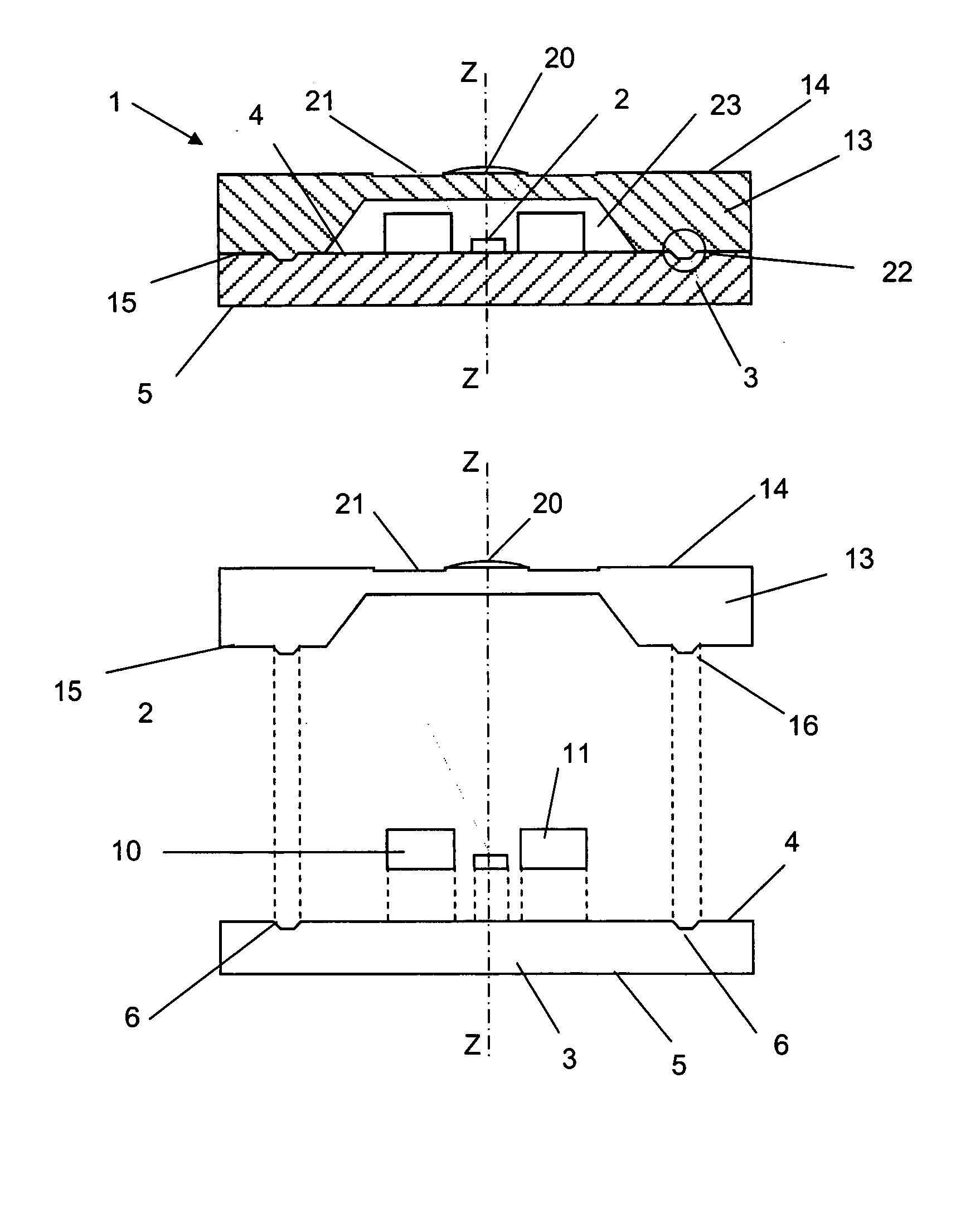
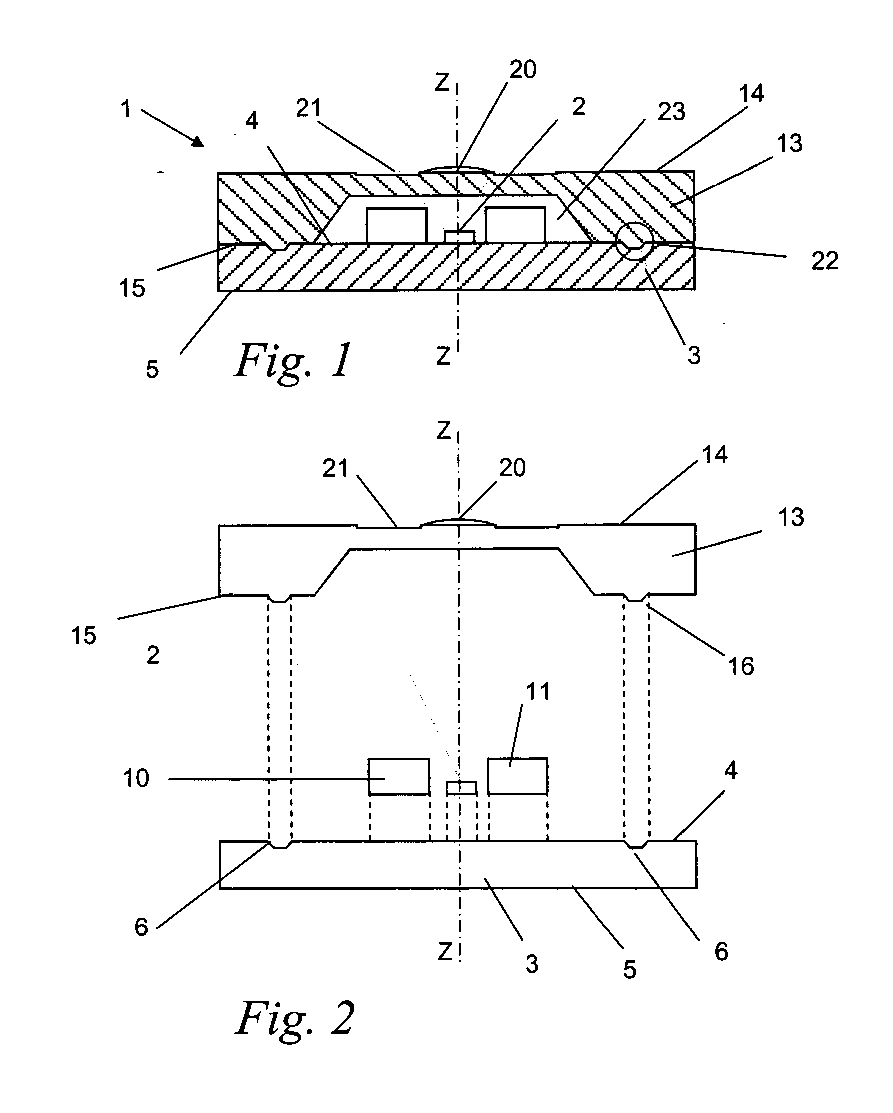
[0040] With reference to such figures, and in particular to the embodiment of FIG. 1, reference 1 globally and schematically indicates a package for housing at least one electro-optic element 2.

[0041] The package 1 has a substantially flat sandwich-like structure and has a vertical axis Z-Z. The word vertical is intended with reference to the orientation of the package 1 in the annexed figures.

[0042] The electro-optic element 2 can be a VCSEL, a PIN or a photo-detector, an APD or a LED depending on the functionality of the electro-optic module wherein such element is inserted.

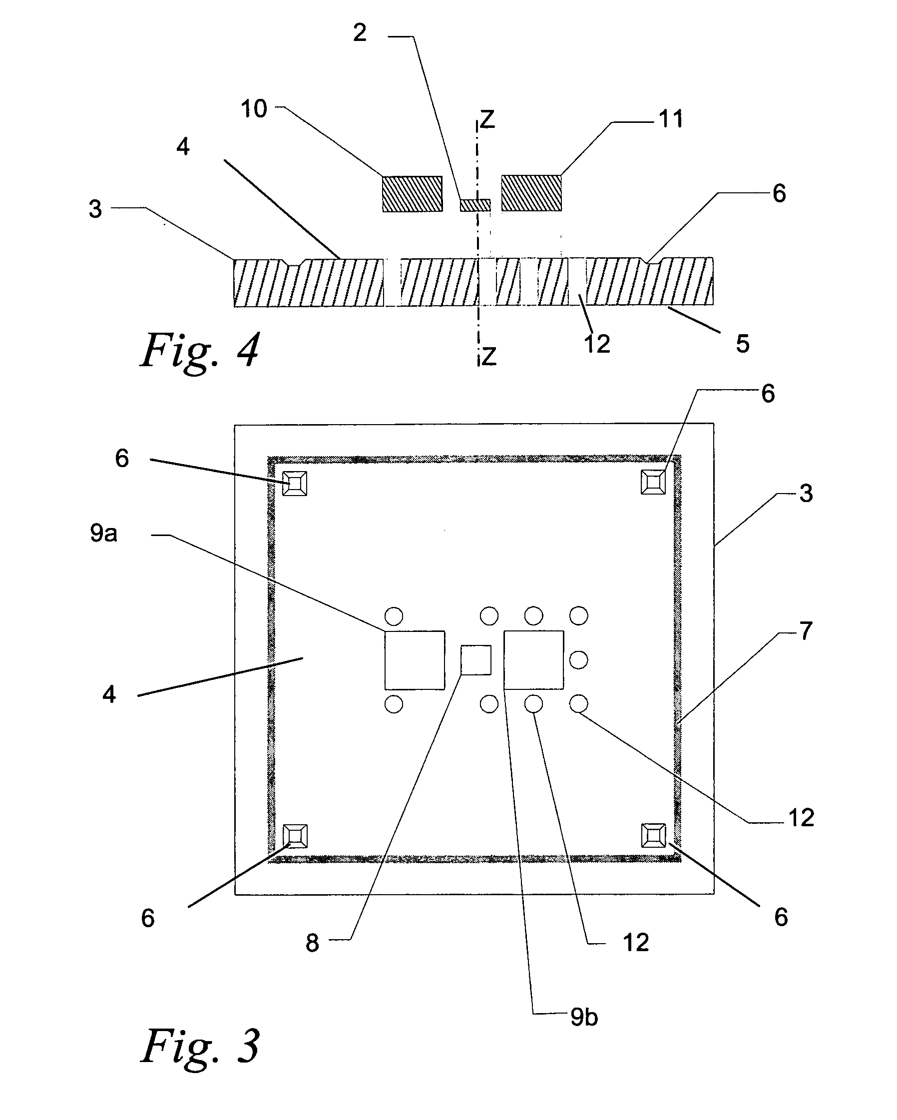
[0043] The package 1 comprises a bearing element 3 preferably made of a silicon die, with an upper surface 4 and a lower surface 5. In a preferred embodiment, the silicon die is substantially flat and square-shaped.

[0044] As it can be seen from FIG. 3, the upper surface 4 has a metallic pad 8 (substantially square-shaped in the figure embodiment ) apt to enable the positioning and the fixing, by welding, of...


PUM


Abstract

A package houses at least one electro-optic active element for transmission using an optical fiber. The package has a bearing element for the at least one electro-optic active element. Advantageously, the package has a sandwich-like structure and includes a closing element associated with the bearing element using a suitable aligning and coupling device to define a hermetically closed housing seat. Moreover, the closing element houses a lens in axial alignment with the electro-optic active element. An electro-optic module includes the package associated with a casing having a receptacle housing an optical fiber.

Description

PRIORITY CLAIM [0001] The present application claims priority from European Patent Application No. 04425400.1 filed May 31, 2004, the disclosure of which is hereby incorporated by reference. BACKGROUND OF THE INVENTION [0002] 1. Technical Field of the Invention [0003] The present invention relates to a package for housing at least one electro-optic active element, an electro-optic module, be it either a transmitter or a receiver, of the type used in the field of telecommunications by optical fiber transmission, and relative assembling method. [0004] 2. Description of Related Art [0005] As it is well known, the recent years have seen the development of data transmission on optical fibers, in the technical field of telecommunications . [0006] Optical fibers are used for transmitting information through light pulses, in the infrared field, by means of a very thin glass or plastic fiber cable. The pulses are transmitted from the centre of the fiber, called nucleus or “core”, which is su...

Claims


Application Information

Patent Timeline
IPC IPC(8): G02B6/42H01L31/0203
CPCG02B6/4248G02B6/4201G02B6/424G02B6/4251G02B6/4245G02B6/4256G02B6/4274
Inventor FINCATO, ANTONIO
Owner STMICROELECTRONICS SRL
Learn More