Method for forming outer packaging body of product

a technology for outer packaging and products, which is applied in the direction of cell components, jackets/cases materials, electrical apparatus casings/cabinets/drawers, etc., can solve the problems of unsatisfactory dust-proof and drip-proof performance, undesirable increase in the volume and weight of the pack case, and the entire battery pack

Inactive Publication Date: 2005-04-19
PANASONIC CORP
View PDF11 Cites 18 Cited by
  • Summary
  • Abstract
  • Description
  • Claims
  • Application Information

AI Technical Summary

Benefits of technology

[0012]According to the above-described apparatus, by driving the resin injection nozzle to move toward the main mold housing the object to be resin-sealed, the core is pressed on the main mold against an energizing force exerted by the elastic member, thereby closing the main mold. Thus, resin poured through the resin injection nozzle is charged in the charging space. The produc

Problems solved by technology

However, a conventional outer packaging body cannot be constructed without performing bonding of separate cases.
This leads to an undesirable increase in the volume and weight of the pack case, namely, the entire battery pack.
As a c

Method used


Image

  • Method for forming outer packaging body of product
  • Method for forming outer packaging body of product
  • Method for forming outer packaging body of product

Examples


first example

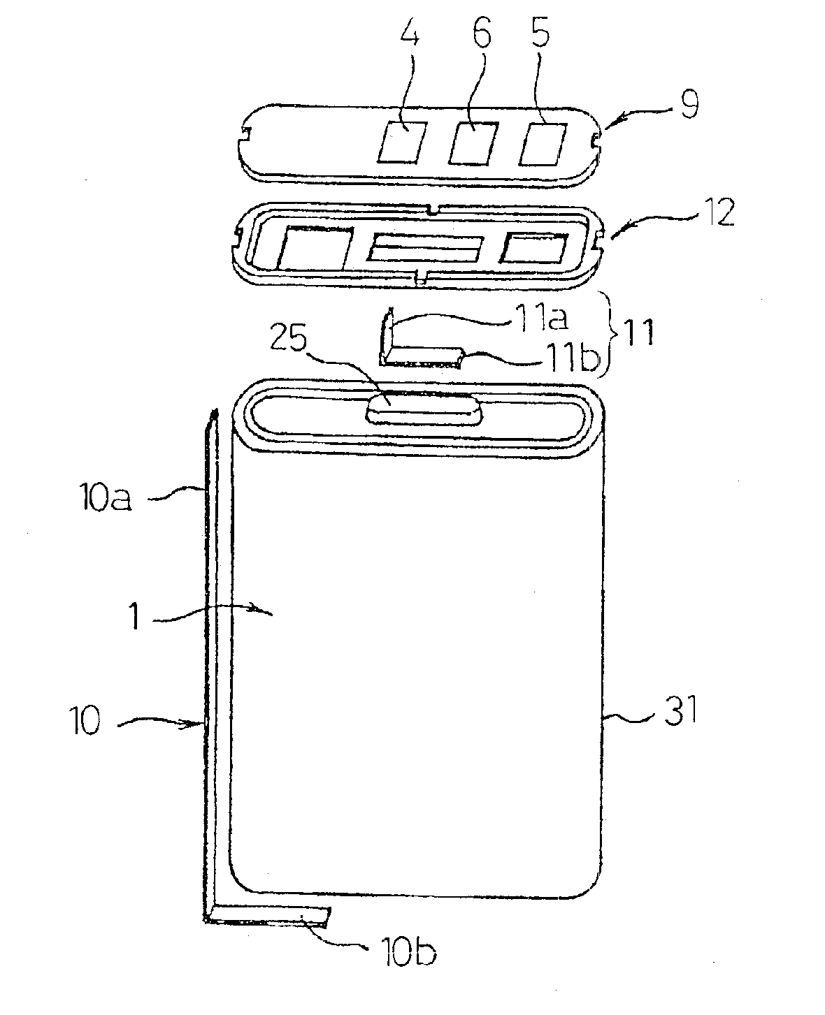
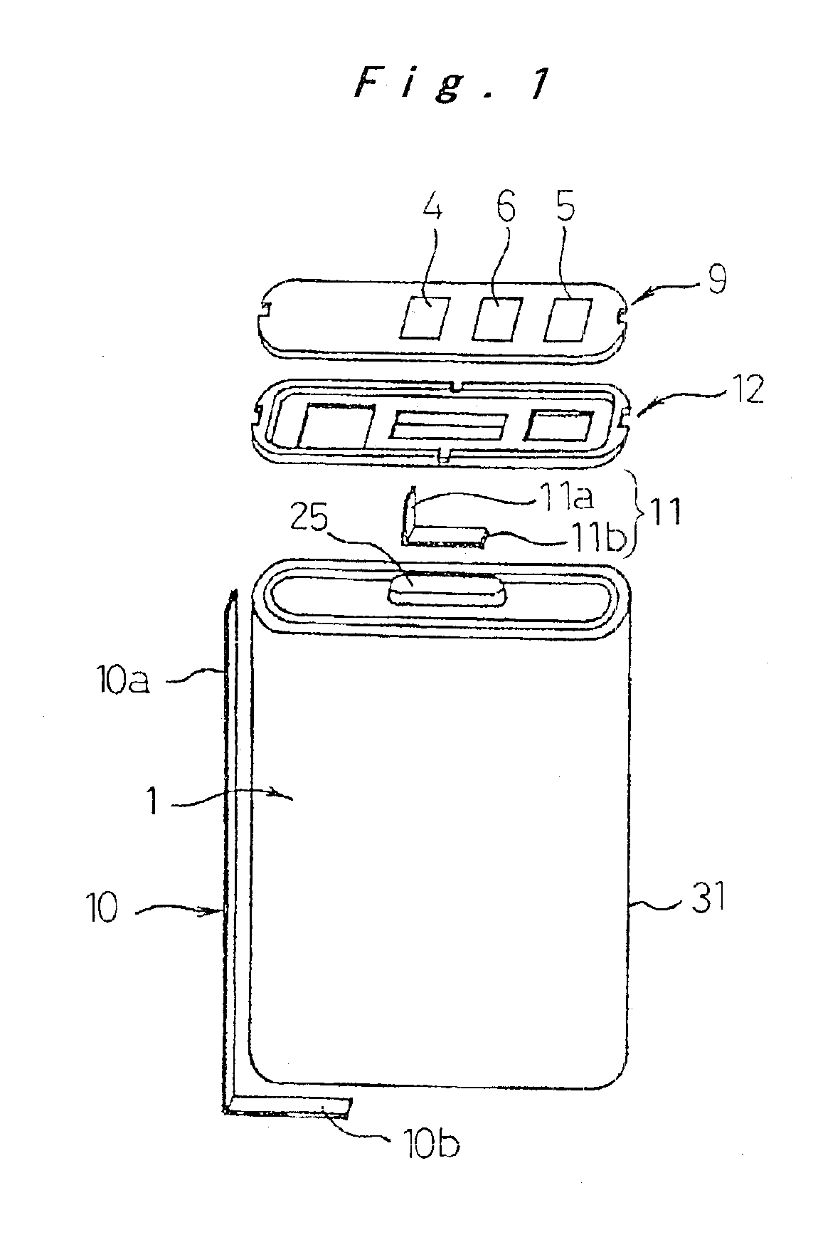
[0038]There is prepared a mold whose content volume is set in conformity with the outer dimensional configuration of the pack case 7. The mold is provided with a protrusion necessary for forming three openings: a plus terminal window 34 at a position corresponding to the plus terminal 4; a minus terminal window 35 at a position corresponding to the minus terminal 5; and a temperature detecting terminal window 36 at a position corresponding to the temperature detecting terminal 6. The intermediate product 50 is arranged, in a suspended state, within the mold with use of a slender supporting member. Subsequently, molten resin is poured into the mold.

[0039]Since the intermediate product 50 has a single-piece structure with a slight gap left, the injected resin is filled in a gap between the mold and the intermediate product 50. After performing curing, the resin is taken out of the mold, whereupon the pack case 7 is constructed that encloses the intermediate product 50. As shown in FIG...

second example

[0042]As shown in FIGS. 5A to 5C, an outer packaging case 51 is formed by resin molding. The outer packaging case 51 has the shape of a bottomed prismatic sleeve, and its depth H is made slightly longer than the entire length of the intermediate product 50. As shown in FIG. 5A, on the bottom surface of the outer packaging case 51 are formed a plus terminal window 34; a minus terminal window 35; and a temperature detecting terminal window 36 so as to correspond to the plus terminal 4, the minus terminal 5, and the temperature detecting terminal 6, respectively, of the intermediate product 50.

[0043]As shown in FIGS. 6A to 6C, the intermediate product 50 is inserted into the outer packaging case 51. The plus terminal 4, the minus terminal 5, and the temperature detecting terminal 6 are exposed from their corresponding openings: the plus terminal window 34; the minus terminal window 35; and the temperature detecting terminal window 36, respectively. Subsequently, molten resin is filled ...

third example

[0045]As shown in FIGS. 7A to 7D, an outer packaging case 52 is formed, in the shape of a bottomed prismatic sleeve, by resin molding. The intermediate product 50 is inserted into the outer packaging case 52, with its circuit board 9 facing the open end. Thereafter, a mold is arranged for forming a plus terminal window 34; a minus terminal window 35; and a temperature detecting terminal window 36 at the open end of the outer packaging case 52, and for sealing up the open end. Subsequently, molten resin is filled in a space around the open end, followed by curing. Whereupon, as shown in FIG. 7D, the plus terminal window 34; the minus terminal window 35; and the temperature detecting terminal window 36 are formed.

[0046]The open end of the outer packaging case 52 is sealed up, so that, as shown in FIG. 3, the plus terminal 4, the minus terminal 5, and the temperature detecting terminal 6 are exposed externally from the plus terminal window 34, the minus terminal window 35, and the temp...


PUM

PropertyMeasurementUnit
Temperatureaaaaaaaaaa
Hardnessaaaaaaaaaa

Abstract

An intermediate product is formed by combining together plurality of constituent elements. The intermediate product is arranged in a mold an then molten resin is charged in the mold. An opening is formed so as to correspond to a plus terminal, a minus terminal, and a temperature detecting terminal in the intermediate product, and its periphery is covered with the resin. Whereupon, a thin enclosed outer packaging body is realized that is made compact and offers excellent dust-proof, drip-proof structure. Alternatively, the intermediate product is housed in an outer packaging case having an open end that allows insertion of the intermediate product, and resin is charged in the open end, thereby achieving sealing.

Description

TECHNICAL FIELD[0001]The present invention relates to a method and an apparatus for forming a product's outer packaging body by covering constituent elements of a product with molten resin, followed by curing the resin.BACKGROUND ART[0002]Not only compactness, slimness, and weight reduction, but also a dust-proof, drip-proof structure or resistance to dropping and impact, have been sought after in such products as portable electronic appliances, due to their necessarily transportable nature and the changing environment in which they may be used. The outer packaging body structure for a product is of particular importance to satisfy these requirements. FIGS. 16A through 16C show an example of such a product. This is a battery pack for use as a power source in a portable electronic appliance. The battery pack is constructed by housing a rechargeable battery 80 and a circuit board 84, which constitutes a battery protective circuit and the like, in an outer packaging body.[0003]The oute...

Claims


Application Information

Patent Timeline
IPC IPC(8): B29C45/14B29C70/00B29C70/88B29C70/72H01M2/00H01M2/02H01M2/16H05K5/00B29C45/27H01M10/052H01M50/103H01M50/121
CPCB29C45/14336B29C45/2701H01M2/0275H01M2/0277H01M2/08H01M2/0207B29C45/14639B29L2031/3468B29L2031/7146H01M10/052H01M2/0217Y02E60/10H01M50/103H01M50/121H05K5/00
Inventor IWAIZONO, YOSHINORIKONISHI, SHOJIISHIMARU, TAKESHI
Owner PANASONIC CORP
Why Eureka
Try Eureka