Method for robotically cleaning compressor blading of a turbine

a turbine blade and robotic cleaning technology, applied in the direction of non-positive displacement fluid engines, hair combs, solid removal, etc., can solve the problems of blade and casing surface finish deterioration, turbine loss, and turbine blade damage,

Inactive Publication Date: 2005-04-26
GENERAL ELECTRIC CO
View PDF9 Cites 32 Cited by
  • Summary
  • Abstract
  • Description
  • Claims
  • Application Information

AI Technical Summary

Benefits of technology

[0004]In accordance with a preferred embodiment of the present invention, there is provided a robotic system for cleaning compressor blading of various stages of the compressor utilizing a spray head at controlled cleaning locations within the stages of the compressor blading in combination with robotic manipulation of the spray head through the complex compressor geometry, enabling blade contour following that will permit cleaning of areas of blades traditionally inaccessible, absent removal of the compressor casing. Further, the compressor cleaning apparatus of the present invention enables performance of the cleaning process remotely from the compressor bell mouth inlet while the turbine is shut down and remains fully assembled. Consequently, the cleaning apparatus is designed for use at normal turbine shutdown or maintenance intervals such that the performance gains are optimally sustained throughout the turbine life cycle. In comparison with offline compressor water wash processes, the present invention affords about a 1% increment in output improvement.

Problems solved by technology

Fundamentally, losses in the compressor and turbine are caused by a deterioration of blade and casing surface finishes, blade shape profile changes, rubs and other flow path distortions.
Power and efficiency are reduced as a result of these frictional and aerodynamic changes.
While these processes are generally effective, there are still residual losses after cleaning.
Consequently, at present, these residual losses are addressed only by removal of casings and aggressive restoration work or parts replacement, all of which are costly.

Method used


Image

  • Method for robotically cleaning compressor blading of a turbine
  • Method for robotically cleaning compressor blading of a turbine
  • Method for robotically cleaning compressor blading of a turbine

Examples


Embodiment Construction

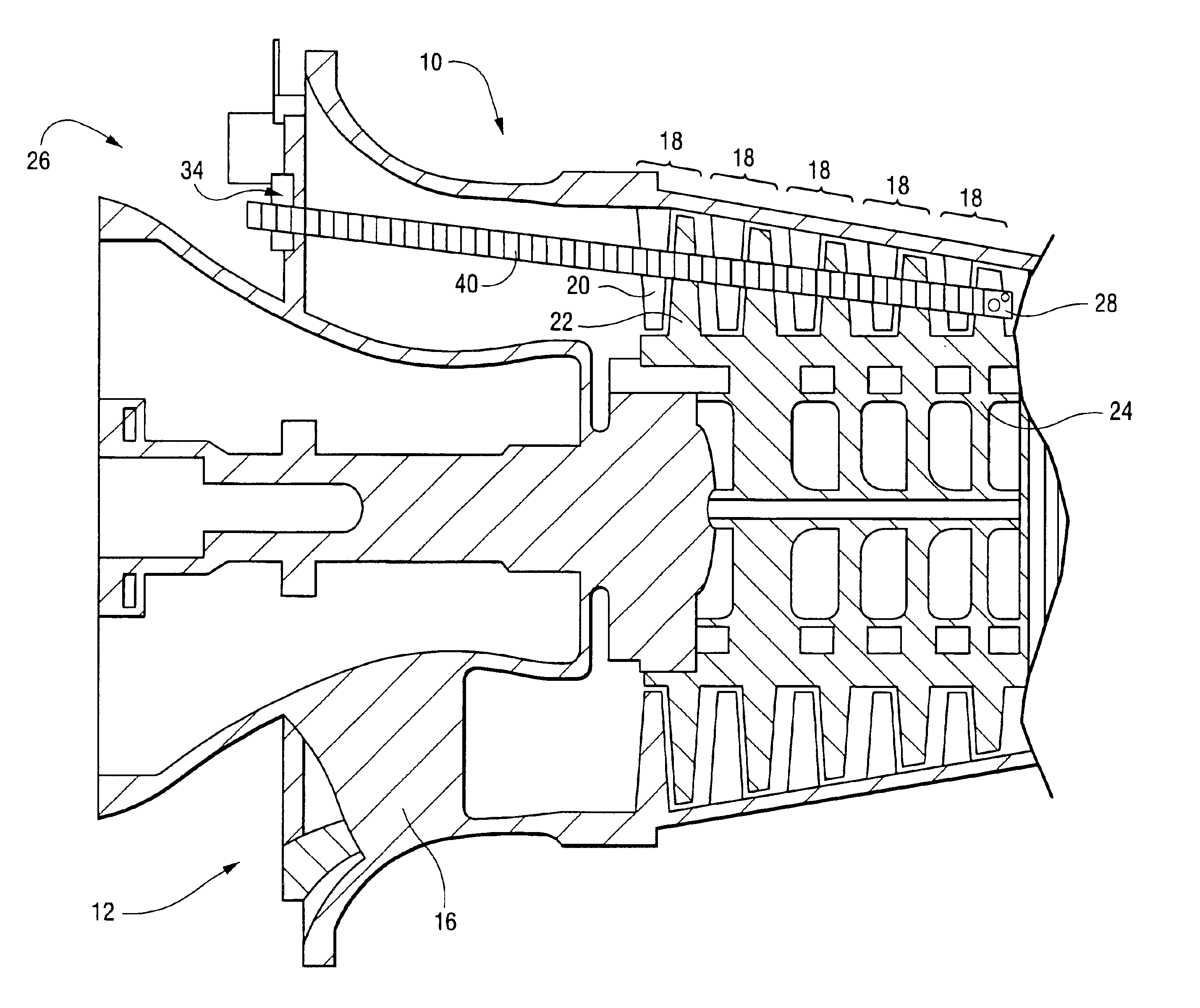
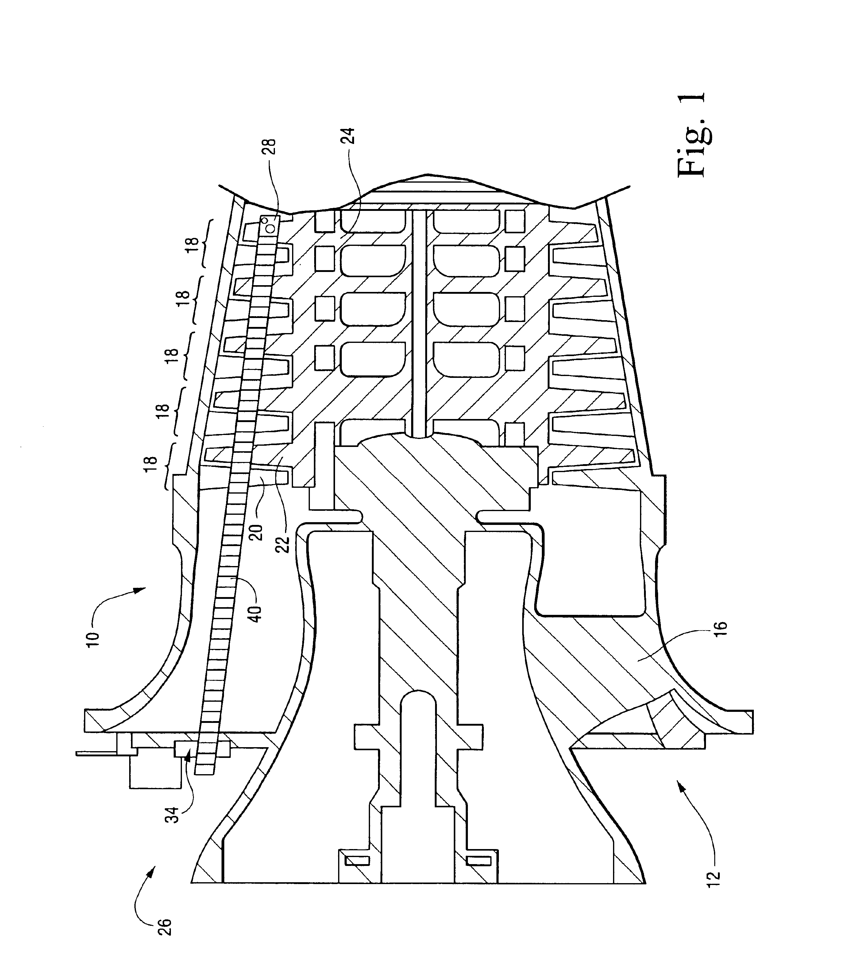
[0027]Referring now to FIG. 1, there is illustrated a portion of a compressor, generally designated 10, having an inlet 12 in the shape of a bell mouth 14, a single steerable vane 16 of a plurality of circumferentially spaced steerable vanes being illustrated in the bell mouth 14. A number of stages 18 are illustrated with each stage including non-rotatable circumferentially spaced stator blades 20 extending generally radially inwardly from the compressor casing and a plurality of circumferentially spaced blades 22 mounted on the rotor 24. It will be appreciated that the rotational position of the rotor blades vis-a-vis the position of the stator blades during an outage is random.

[0028]Also illustrated in FIG. 1 is a compressor blade cleaning system, generally designated 26. The system 26 is mounted adjacent the inlet 12 and includes a cleaning head 28 positioned adjacent a selected blade among the blades of the various stages for applying a cleaning fluid to the selected blade. As ...


PUM

PropertyMeasurementUnit
flexibleaaaaaaaaaa
speedaaaaaaaaaa
cranking speedaaaaaaaaaa

Abstract

The compressor cleaning system includes a track mounted about the inlet of the compressor. A circumferential position assembly mounts an insertion drive assembly which is driven about the track into selected circumferential positions. The insertion drive assembly carries a manipulator arm assembly mounting at its distal end a cleaning head. By using pairs of control cables, the proximal yaw, pitch and distal yaw sections of the manipulator arm can be moved to weave the cleaning head past the multiple stages of blading to locate the cleaning head adjacent a selected blade. By repeated extension and retraction of the cleaning head relative to the compressor inlet and about the compressor blades, each blade can be cleaned without disassembly of the compressor casing or removal of the rotor.

Description

BACKGROUND OF THE INVENTION[0001]The present invention is directed to apparatus for cleaning the compressor blades of a turbine and particularly relates to apparatus for robotic washing of the compressor blading of a plurality of compressor stages by accessing the blading through the compressor inlet and without disassembly of the compressor casings or removal of the compressor rotor.[0002]Turbines, for example, gas turbines, undergo changes in performance over time. Fundamentally, losses in the compressor and turbine are caused by a deterioration of blade and casing surface finishes, blade shape profile changes, rubs and other flow path distortions. Power and efficiency are reduced as a result of these frictional and aerodynamic changes. The majority of the aggregate losses are attributable to the compressor.[0003]Turbine performance can be recovered to varying degrees by compressor washing processes designed to remove fouling and-deposition on the compressor blading. Current pract...

Claims


Application Information

Patent Timeline
Patent Type & Authority Patents(United States)
IPC IPC(8): F04D29/00B08B9/00F01D25/00F04D29/70
CPCB08B9/00F04D29/70F01D25/002
Inventor TRAVALY, ANDREW JOSEPHLOPES, WILLIAM FRANCISBENTZEL, KATHLEEN LYNNE
Owner GENERAL ELECTRIC CO
Why Eureka
Try Eureka