Multidirectional turbine shim seal

a turbine and shim seal technology, applied in the field of sealing systems, can solve the problems of reducing the efficiency of the turbine, difficult to manufacture complex seals with dimensions corresponding to such small openings, and difficult to seal such small openings with relatively inflexible seals, such as the seal disclosed in mori

Inactive Publication Date: 2005-04-26
SIEMENS ENERGY INC
View PDF68 Cites 54 Cited by
  • Summary
  • Abstract
  • Description
  • Claims
  • Application Information

AI Technical Summary

Benefits of technology

[0013]An advantage of this invention is that the turbine seal may be positioned in a turbine assembly so that a longitudinal axis of the turbine seal is generally transverse to the axial direction of the turbine blade assembly.
[0014]Yet another advantage of this invention is that this invention provides a turbine seal that is flexible and capable of absorbing vibrations typically encountered during turbine operation.

Problems solved by technology

Such leakage reduces the efficiency of the turbine and can lead to harmful results.
Sealing such small openings with relatively inflexible seals, such as the seals disclosed in Mori, is challenging.
Furthermore, manufacturing complex seals with dimensions corresponding to such small openings is difficult at least because of the increased difficulty encountered in manufacturing complex aspects of such seals.
3(b) and identified as element 16, in seals having such small dimensions is difficult and costly.

Method used


Image

  • Multidirectional turbine shim seal
  • Multidirectional turbine shim seal
  • Multidirectional turbine shim seal

Examples


Embodiment Construction

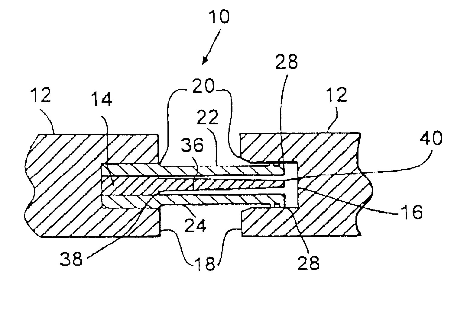
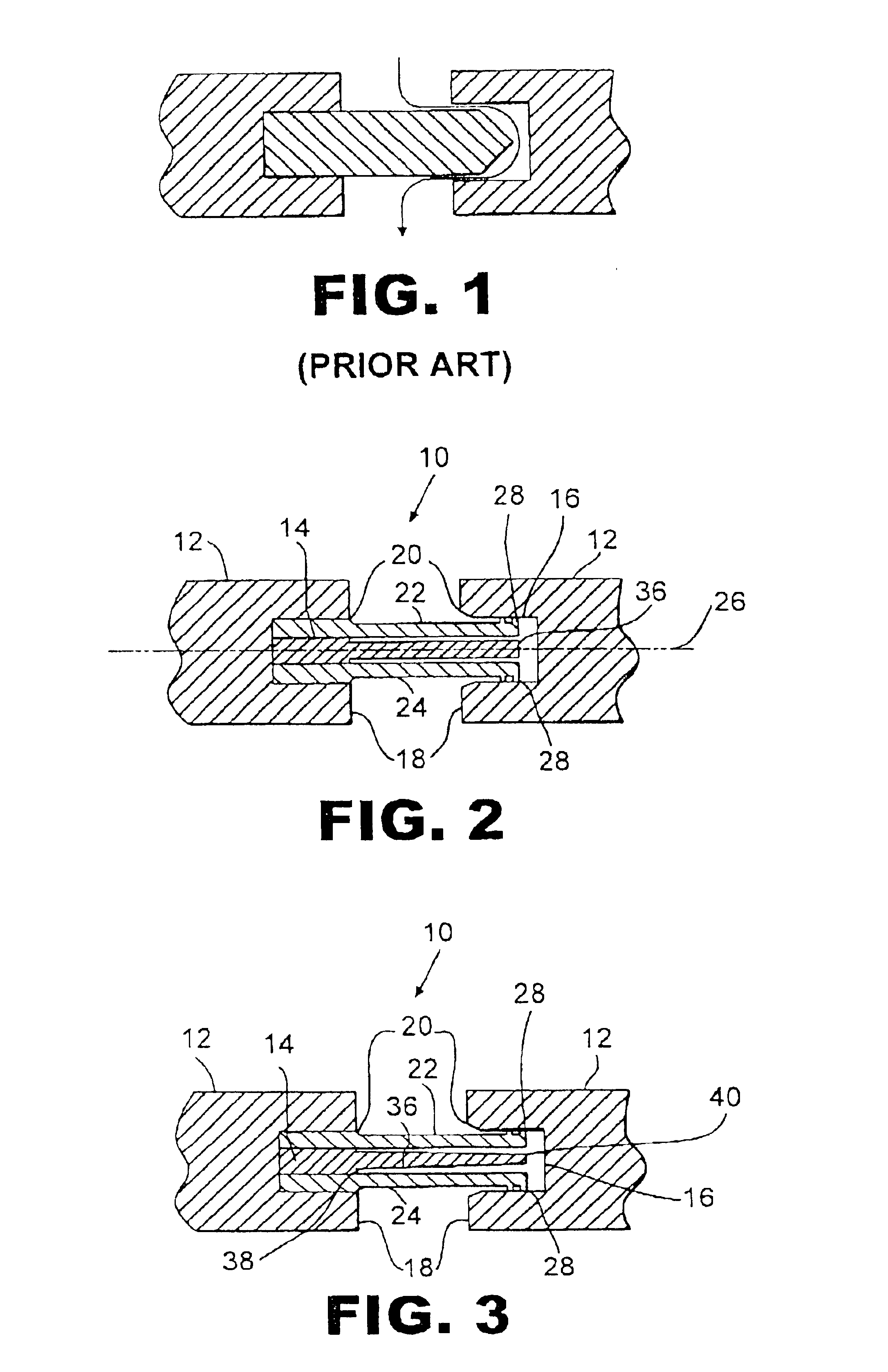
[0020]The turbine seal 10 of this invention is usable to seal turbine components 12 together at various locations throughout a turbine assembly. As shown in FIG. 2, the turbine seal 10 includes a main body 14 having multiple arms extending from the main body 14 to engage a surface 16 of a turbine. The turbine seal 10 may be composed of any materials suitable for sealing fluids in turbines. These materials may differ, as evident to those skilled in the art, depending on the application of the turbine. In the embodiment shown in FIG. 2, the turbine components are protrusions 18 coupled to adjacent turbine blades. The protrusions include recesses 20, which may otherwise be referred to as grooves.

[0021]While this invention is shown positioned in contact with turbine components having certain configurations, this invention is not limited to use with such a turbine configuration. Rather, this invention may be used in any situation where a seal is needed to prevent or significantly restric...


PUM


Abstract

A turbine seal closure mechanism for sealing an opening in a turbine component or between one or more turbine components. The turbine seal may include a main body having a longitudinal axis positioned transverse to the axial direction of the turbine and having at least one arm for sealing the main body to a surface of a turbine component and configured to fit within a recess in a turbine component. The turbine seal may also have one or more arms coupled to a side of the main body opposite to the first side having arms attached thereto for sealing the turbine seal to another turbine surface.

Description

CROSS REFERENCE TO RELATED APPLICATIONS[0001]Not ApplicableSTATEMENT REGARDING FEDERALLY SPONSORED RESEARCH[0002]Not ApplicableFIELD OF THE INVENTION[0003]The present invention relates in general to sealing systems and, more particularly, to sealing systems for sealing gaps within a single turbine component or between two or more turbine components.BACKGROUND OF THE INVENTION[0004]In the art of turbine design, the need often exists to seal connections between adjacent turbine components, such as turbine blades, in order to separate fluids and to maintain a turbine's efficiency. For instance, it is desirable to separate pressurized air from hot gases in specific locations in a turbine assembly. A common location for separating these gases is at the intersection between adjacent turbine blades proximate to a turbine housing to which the turbine blades are connected.[0005]Typically, baffles, or “key seals,” are implemented, as shown in FIG. 1, to separate cooled air located in interior...

Claims


Application Information

Patent Timeline
Patent Type & Authority Patents(United States)
IPC IPC(8): F01D11/00F16J15/08F01D25/00F02C7/28
CPCF01D11/005F16J15/0887F05D2240/55F16J15/08
Inventor SMED, JAN P.
Owner SIEMENS ENERGY INC
Why Eureka
Try Eureka