
Display apparatus

Inactive Publication Date: 2005-04-26
CANON KK
View PDF8 Cites 9 Cited by
  • Summary
  • Abstract
  • Description
  • Claims
  • Application Information

AI Technical Summary

Benefits of technology

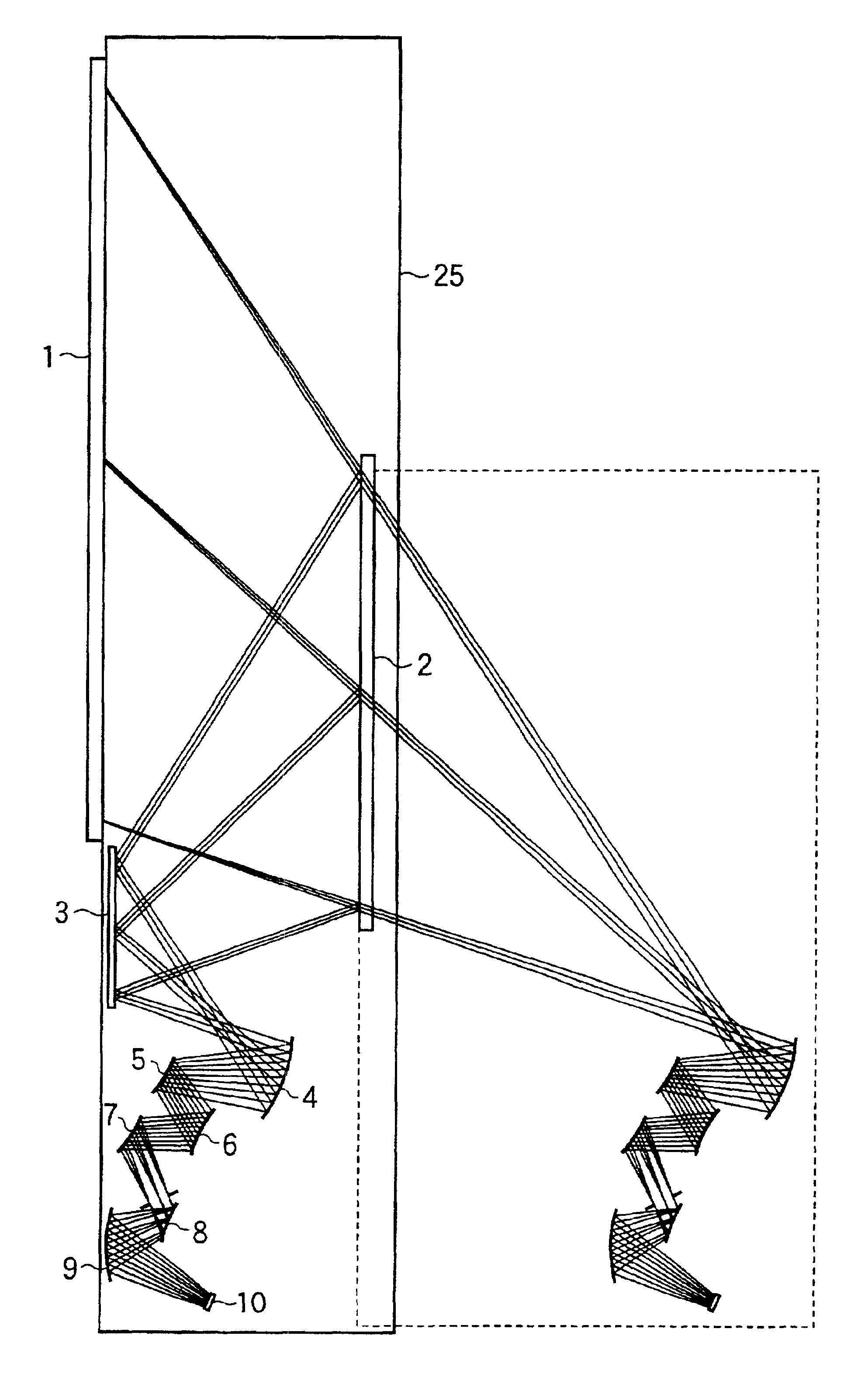
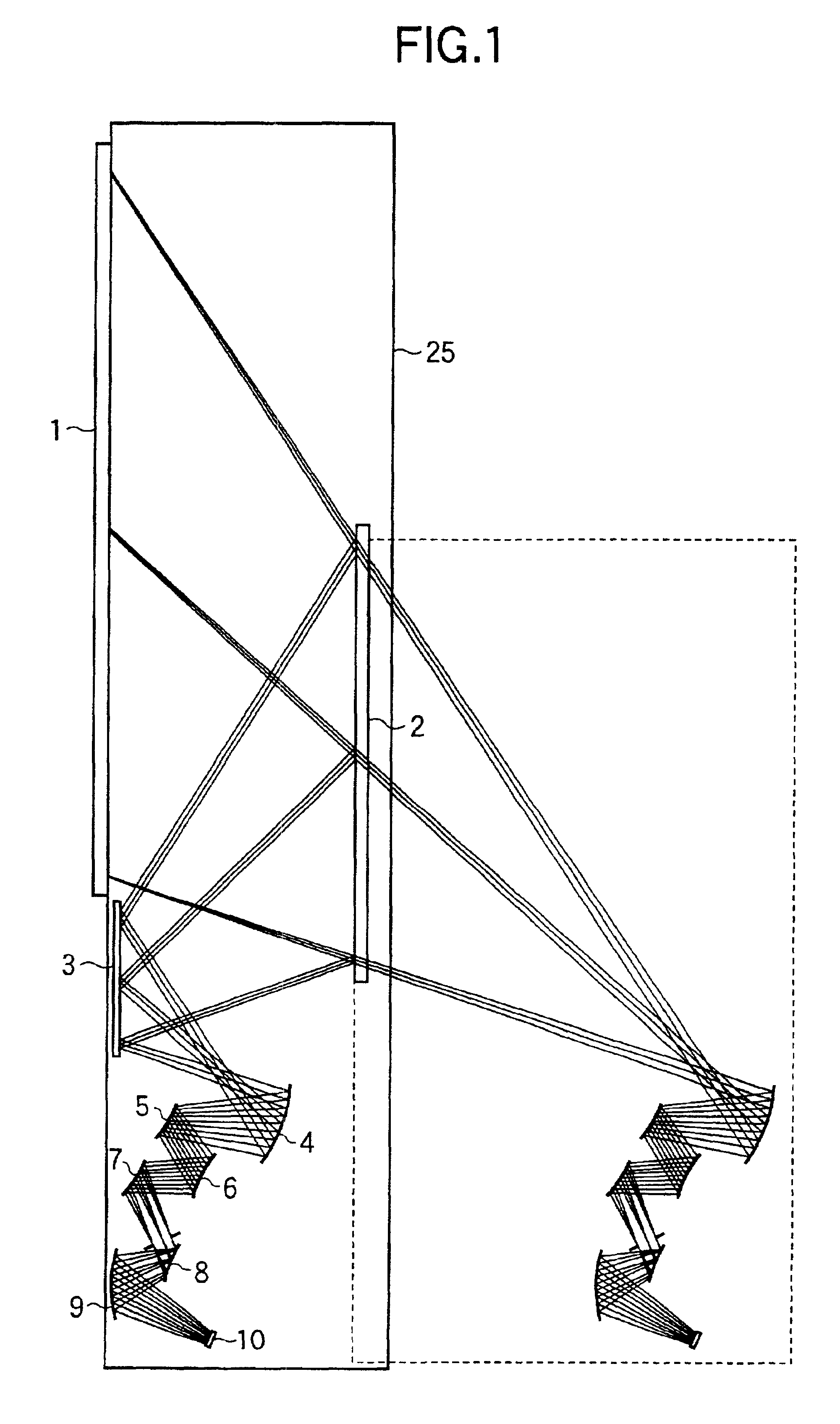
[0009]The present invention has been made to solve the above problems, and has as its object to provide a high-quality, high-precision, large-screen display apparatus which can obtain a sufficient light beam reception angle with respect to an image display unit, improve imaging performance, and obtain an ultra-low-profile structure.

Problems solved by technology

When embodiments in the above prior art are traced and examined, it was found that a reception angle (corresponding to FNO) for a light beam emerging from an image display panel is a tradeoff for imaging performance (distortion characteristics, in particular), and it was difficult to obtain satisfactory optical performance.

Method used


Image

  • Display apparatus
  • Display apparatus
  • Display apparatus

Examples


first embodiment

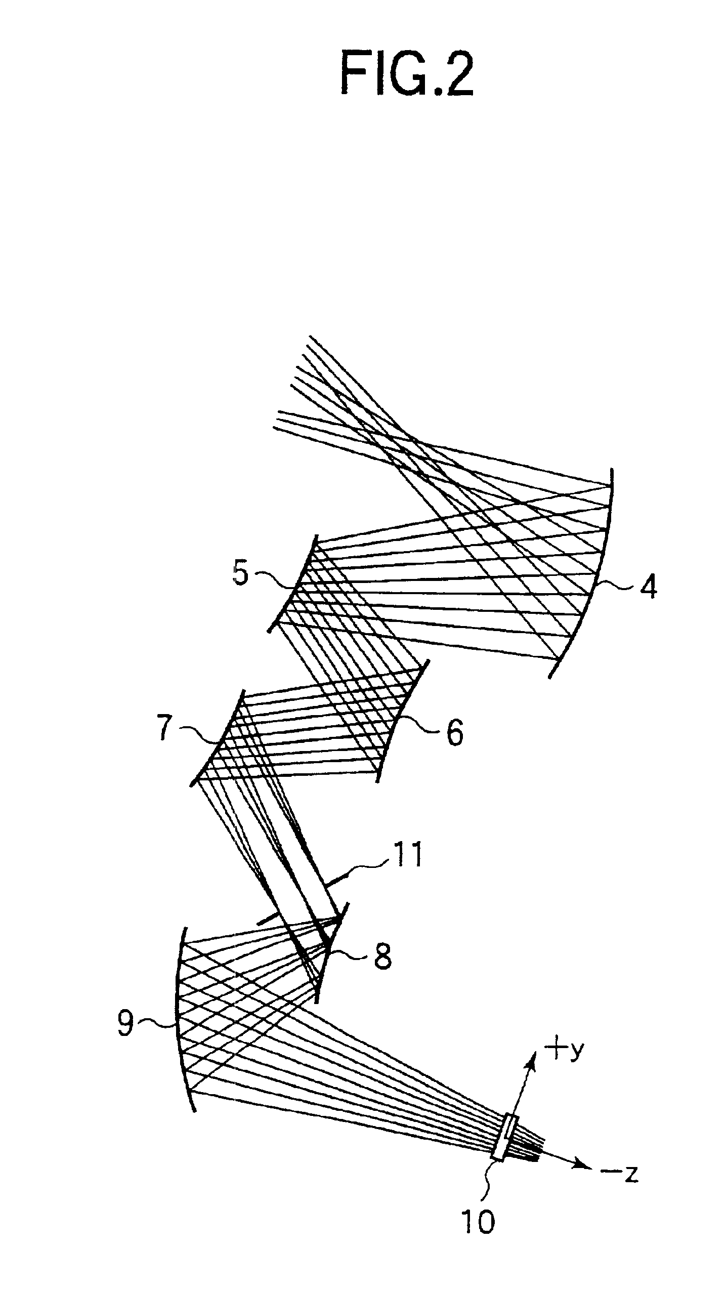
[0047]FIG. 1 is a sectional view showing the arrangement of a thin rear projection display apparatus according to the first embodiment of the present invention. Referring to FIG. 1, this apparatus includes an oblique incident screen 1, AL-deposited plane mirrors 2 and 3, AL-deposited free-form mirrors 4, 5, 6, 7, 8, and 9 which are rotationally asymmetric aspherical curved mirrors, a liquid crystal display device 10, and a casing 25. Note that the rectangular portion surrounded by the dashed line in FIG. 1 is a portion that is additionally written to facilitate the understanding of an oblique incident projection system basic to the present invention, and a rendering of projection without the plane mirrors 2 and 3.

[0048]Although FIG. 1 does not show parts other than those described above, the liquid crystal display device 10 is illuminated from the rear by an illumination system (not shown), and image light emerging from the front surface of the liquid crystal display device 10 trave...

second embodiment

[0063]FIG. 4 is a sectional view showing the arrangement of a thin rear projection display apparatus according to the second embodiment of the present invention. Referring to FIG. 4, this apparatus includes an oblique incident screen 23, AL-deposited plane mirror 24, Al-deposited free-from mirrors 15, 16, 17, 18, 19, and 20, DMD display device 21, and casing 26. Note that as DMD display devices, for example, the devices disclosed in Japanese Patent Nos.2664300, 2978224, and 2978285are widely known.

[0064]Although FIG. 4 does not show parts other than those described above, the DMD display device 21 is illuminated from an upper side by an illumination system (not shown), and image light reflected from the DMD display device 21 travels toward the free-form mirror 20. As in the above embodiment, a light beam travels while being sequentially reflected by the free-form mirrors 15, 16, 17, 18, 19, and 20 is finally reflected by the mirror 20 to emerge toward the plane mirror 24, as shown i...


PUM


Abstract

It is an object of this invention to provide a high-quality, high-precision, large-screen display apparatus which can obtain a sufficient light beam reception angle with respect to an image display unit, improve imaging performance, and obtain a thin structure. There is provided a display apparatus for obliquely projecting light from an image display unit onto a projection optical system, wherein the projection optical system includes a plurality of aspherical curved mirrors and projects an image without distortion (1.2% or less).

Description

BACKGROUND OF THE INVENTION[0001]1. Field of the Invention[0002]The present invention relates to an oblique projection type display apparatus and, more particularly, to a rear projection display apparatus designed to attain a reduction in depth of the apparatus by oblique projection.[0003]2. Related Background Art[0004]A conventional apparatus of this type is disclosed in WO 97 / 01787 or the like. FIG. 6 shows the arrangement of a projection optical system. The conventional technique shown in FIG. 6 is designed to obliquely project an image of an image display panel onto a screen without any trapezoidal distortion by using three to four coaxial aspherical reflecting mirrors and one vertical plane mirror.[0005]When embodiments in the above prior art are traced and examined, it was found that a reception angle (corresponding to FNO) for a light beam emerging from an image display panel is a tradeoff for imaging performance (distortion characteristics, in particular), and it was difficu...

Claims


Application Information

Patent Timeline
IPC IPC(8): G02B17/06G02B17/00G03B21/10H04N5/74
CPCG03B21/10G02B17/0663
Inventor KUREMATSU, KATSUMISUNAGA, TOSHIHIRO
Owner CANON KK
Learn More