
Image reading apparatus

Active Publication Date: 2018-09-13
KONICA MINOLTA INC
View PDF0 Cites 6 Cited by
  • Summary
  • Abstract
  • Description
  • Claims
  • Application Information

AI Technical Summary

Benefits of technology

The aim of this patent is to create an image reading device with fewer optical components and better imaging performance.

Problems solved by technology

The reducing optical system has a deep focal depth but is difficult to miniaturize, whereas the equi-magnifying optical system can be miniaturized but has a shallow focal depth.
However, if in such a splitting optical system an equi-magnifying optical system is used to reduce error sensitivity on the side of the light receiving element, a ray of light would enter adjacent optical paths, resulting in an image overlapping at a boundary of a split portion.
As the number of components increases, there are many parts where errors and variations occur.
This makes adjustment of the optical components complicated and invites degraded imaging performance.

Method used


Image

  • Image reading apparatus
  • Image reading apparatus
  • Image reading apparatus

Examples


first embodiment

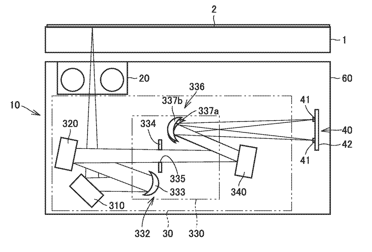
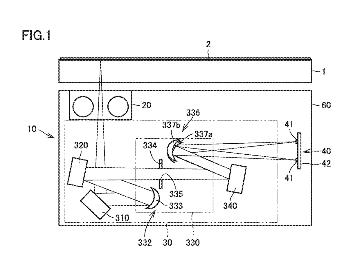
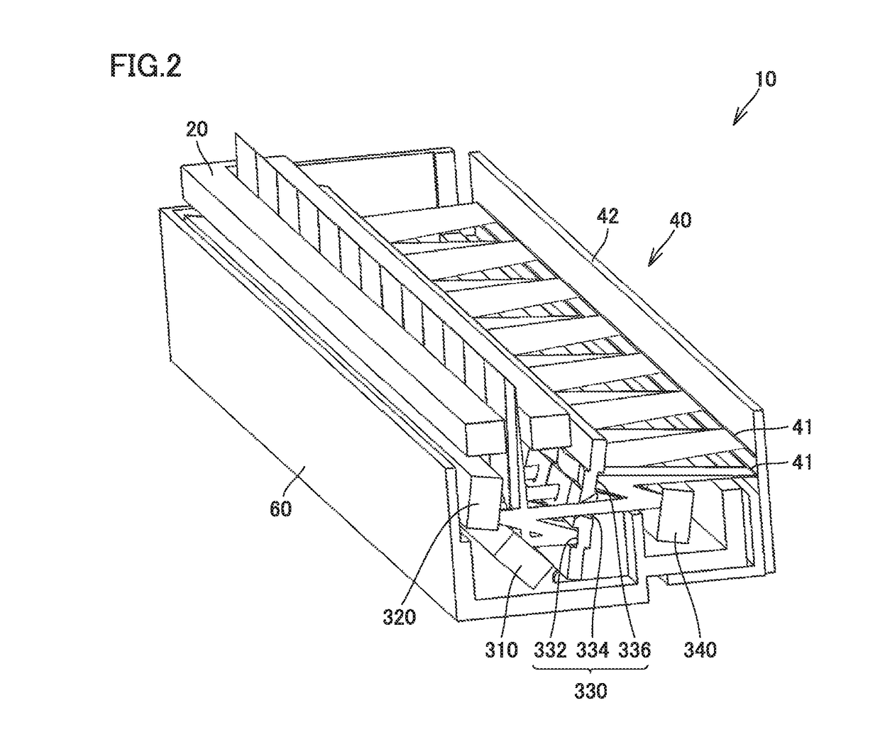
[0024]FIG. 1 is a schematic cross-sectional view of an image reading apparatus according to a first embodiment. FIG. 2 is a schematic perspective view of the image reading apparatus according to the first embodiment. With reference to FIG. 1 and FIG. 2, an image reading apparatus 10 according to the first embodiment will be described.

[0025]As shown in FIGS. 1 and 2, image reading apparatus 10 emits light from a light source 20 to an original 2 serving as an object placed on a platen glass 1 to be read and photoelectrically converts the light that is reflected from the original by a light receiving unit 40 to read image. Image reading apparatus 10 includes light source 20, an optical system 30, light receiving unit 40, and a housing 60. Housing 60 houses light source 20, optical system 30, and light receiving unit 40 therein.

[0026]Light source 20 emits light to expose the object to be read therewith in a main direction (a direction perpendicular to the plane of the sheet of FIG. 1). ...

second embodiment

[0069]FIG. 5 is a schematic cross-sectional view of an image reading apparatus according to a second embodiment. With reference to FIG. 5, an image reading apparatus 10A according to the second embodiment will be described.

[0070]As shown in FIG. 5, linage reading apparatus 10A according to the second embodiment is different front image reading apparatus 10 according to the first embodiment in how an optical system 30A is configured. The remainder in configuration is substantially the same.

[0071]Optical system 30A is configured such that light reflected from original 2 is distributed in a plurality of rows in a direction corresponding to the sub direction and the plurality of distributed rows of light have mutually different optical path lengths. When optical system 30A is compared with optical system 30 according to the first embodiment, the former is different front the latter in how an optical element 330A is configured. The remainder in configuration is substantially the same.

[00...

third embodiment

[0095]FIG. 7 is a schematic cross-sectional view of an image reading apparatus according to a third embodiment. With reference to FIG. 7, an image reading apparatus 10B according to the third embodiment will be described.

[0096]As shown in FIG. 7, image reading apparatus 10B according to the third embodiment is different from image reading apparatus 10 according to the first embodiment in how an optical system 30B is configured. The remainder in configuration is substantially the same.

[0097]Optical system 30B includes reflecting mirrors 350, 360, 370, a lens mirror array 332B, and a lens mirror array 336B.

[0098]Reflecting mirror 350 corresponds to a common reflecting mirror. Reflecting mirror 350 has an upstream reflecting surface 350a and a downstream reflecting surface 350b opposite to each other. Upstream reflecting surface 350a is located upstream of lens mirror array 332B serving as a splitting component on the optical path on which the light reflected from original 2 travels to...


PUM


Abstract

An image reading apparatus includes a light source, a light receiving unit, and an optical system. The light receiving unit includes a plurality of light receiving elements. The optical system includes a plurality of optical components for splitting the light reflected from the object to be read, and guiding the split light to each of the plurality of light receiving elements. The plurality of optical components include a splitting component that splits the light reflected from the object to be read in a direction corresponding to a main direction, and a common component provided with a common portion. The common portion has an optically acting area causing a common effect on the tight split by the splitting component. A cross sectional shape of the optically acting area orthogonal to a direction corresponding to the main direction is the same shape along the direction corresponding to the main direction.

Description

[0001]The entire disclosure of Japanese Patent Application No. 2017-047416, filed on Mar. 13, 2017, is incorporated herein by reference in its entirety.BACKGROUNDTechnological Field[0002]The present invention relates to an image reading apparatus.Description of the Related Art[0003]Conventionally, there are mainly two types of scanners that read an original by a line sensor, i.e., a CCD type (a reducing optical system) and a CIS type (an equi-magnifying optical system). The reducing optical system has a deep focal depth but is difficult to miniaturize, whereas the equi-magnifying optical system can be miniaturized but has a shallow focal depth.[0004]For this reason, the CCD type is a mainstream for a flat bed scanner, whereas the CIS type is often used for reading through an ADF transporting an original In order to eliminate image quality difference between the front and back sides of an original (i.e., between the flat bed and the ADF), a reading module is required which is capable...

Claims


Application Information

Patent Timeline
IPC IPC(8): H04N1/03H04N1/031H04N1/028
CPCH04N1/0305H04N1/0315H04N1/0318H04N1/0306H04N1/02825
Inventor OHZAWA, SATOKOYAMAMURA, AKIRAASAOKA, SHOGOHIGUCHI, YUKI
Owner KONICA MINOLTA INC
Learn More