Thermal flow sensor having sensor and bypass passages

a technology of thermal flow sensor and bypass passage, which is applied in the direction of volume/mass flow measurement, measurement devices, instruments, etc., can solve the problems of too large thermal flow sensor b>101/b> shown in fig. 23 to be used for checking the suction state, and achieve the effect of stably producing measurement outpu

Inactive Publication Date: 2005-05-03
CKD
View PDF17 Cites 39 Cited by
  • Summary
  • Abstract
  • Description
  • Claims
  • Application Information

AI Technical Summary

Benefits of technology

[0011]The present invention has been made in view of the above circumstances and has an object to overcome the above and to provide problems a thermal flow sensor capable of stably producing measurement output even where a flow rate to be measured is high.

Problems solved by technology

As a result, the pressure in the orifice varies between a sucking state and a non-sucking state, so that the pressure sensor could not check the suction state.
However, the above mentioned thermal flow sensor 101 shown in FIG. 23 has a problem of slow response (about 1-2 sec.).
There is also a problem that the thermal flow sensor 101 shown in FIG. 23 is too large to be used for checking the suction state.
It is therefore difficult to utilize the thermal flow sensor 101 for a suction check.
In the thermal flow sensor proposed by the applicant in Japanese patent application No. 2000-368801, however, there is still a problem that the influence of a turbulent flow in a passage become larger as the measured flow rate becomes higher.
In other words, there further occurs a problem that, as the measured flow rate becomes higher, measurement output becomes unstable due to the turbulent flow in the passage.
Consequently, even the thermal flow sensor proposed in Japanese patent application No. 2000-368801 could not sufficiently perform an accurate suction check.

Method used


Image

  • Thermal flow sensor having sensor and bypass passages
  • Thermal flow sensor having sensor and bypass passages
  • Thermal flow sensor having sensor and bypass passages

Examples


first embodiment

[0051](First Embodiment)

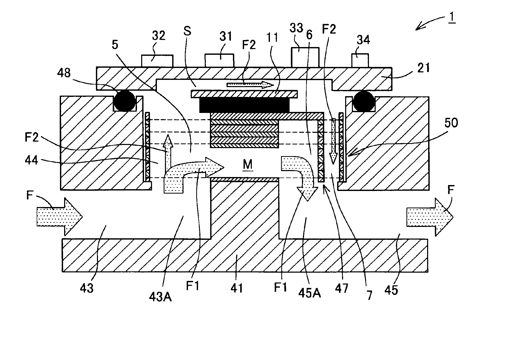
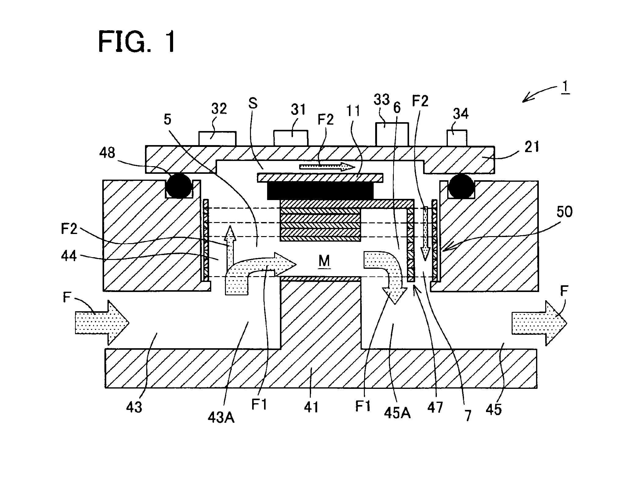
[0052]At first, the first embodiment is explained. FIG. 1 shows a schematic structure of a thermal flow sensor in the first embodiment. As shown in FIG. 1, the thermal flow sensor 1 in the present embodiment includes a body 41, a sensor board 21, and a laminated filter 50. The sensor board 21 is fixed to the body 41 in close contact relation through a gasket 48 by screws while the laminated filter 50 is placed in a passage space 44 of the body 41. Accordingly, a sensor passage S and a main passage M are formed. The main passage M is a bypass passage with respect to the sensor passage S. In other words, the thermal flow sensor 1 in the present embodiment includes the sensor passage and the bypass passage.

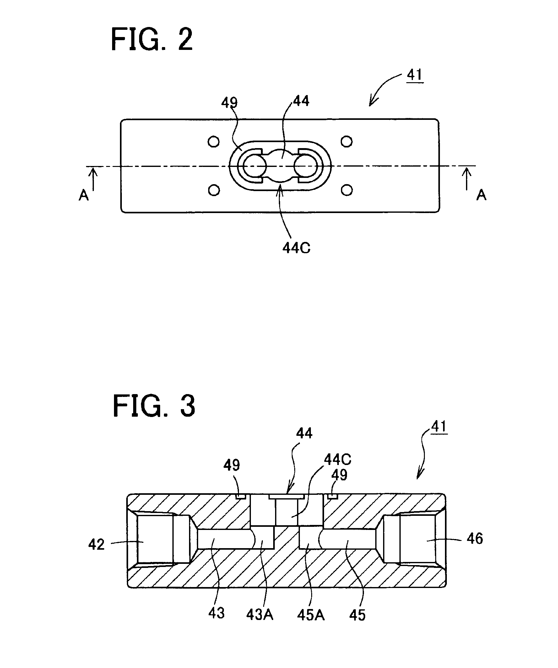
[0053]The body 41 is of a rectangular parallelepiped shape as shown in FIGS. 2 and 3. FIG. 2 is a plane view of the body 41 and FIG. 3 is a sectional view taken along a line A—A in FIG. 2. This body 41 is formed with an inlet port 42 and an outlet port 46 on b...

second embodiment

[0076](Second Embodiment)

[0077]Next, a second embodiment will be explained. FIG. 14 is a schematic structural view of a thermal flow sensor in the second embodiment. As shown in FIG. 14, the thermal flow sensor 201 in the second embodiment has a substantially identical structure to that in the first embodiment, except that a laminated filter 50A is fit in the passage space 44 in place of the laminated filter 50. More specifically, in the thermal flow sensor 201 in the present embodiment, the laminated filter 50A in which the mesh parts 51M are arranged at smaller intervals than those in the laminated filter 50 is fit in the passage space 44. Accordingly, the following explanation is made with a focus on different points from those in the first embodiment. It is to be noted that identical structures as those in the first embodiment are indicated by the same numerals and the explanation thereof is omitted.

[0078]The laminated filter 50A is explained with reference to FIG. 15. The lamin...

third embodiment

[0084](Third Embodiment)

[0085]Next, a third embodiment will be explained. FIG. 16 is a schematic structural view of a thermal flow sensor in the third embodiment. As shown in FIG. 16, the thermal flow sensor 301 in the third embodiment has a substantially identical structure to that in the first embodiment, except that a laminated filter 60 is fit in the passage space 44 in place of the laminated filter 50. In other words, in the thermal flow sensor 301 in the present embodiment, the laminated filter 60 formed with a plurality of grooves is fit in the passage space 44. Furthermore, the laminated filter 60 differs from the laminated filter 50 in the first embodiment in that the filter 60 includes no mesh part 51M.

[0086]Accordingly, the following explanation is made with a focus on different points from those in the first embodiment. It is to be noted that identical structures as those in the first embodiment are indicated by the same numerals and the explanation thereof is omitted.

[0...


PUM


Abstract

A laminated filter is fit in a passage space formed in a body. The laminated filter is made of a mesh plate including a mesh part, a first blocking plate including a blocking part, a second blocking plate including a blocking part, and a third blocking plate including a blocking part which are arbitrarily combined and layered. Accordingly, a three-layered mesh part is placed between a main passage and a sensor passage and a blocking wall is constructed of the three blocking parts.

Description

BACKGROUND OF THE INVENTION[0001]1. Field of the Invention[0002]The present invention relates to a thermal flow sensor for measuring a flow rate by means of hot wires, and more particularly to a thermal flow sensor capable of reducing a turbulent flow which occurs in a passage in order to stabilize measurement output.[0003]2. Description of Related Art[0004]As one of conventional thermal flow sensors for measuring a flow rate by using hot wires, there is a thermal flow sensor provided with a measuring chip manufactured by a semiconductor micro-machining technology as a sensor part. An example of this type of thermal flow sensor is shown in FIG. 23. In a thermal flow sensor 101 in FIG. 23, a gas to be measured is caused to flow in an inlet port 102, is made into a laminar flow by a laminar flow mechanism 103, and is caused to pass through a measuring passage 104 and flow out through an outlet port 105. For measurements of the flow rate of the gas, a measuring chip 111 connected to an...

Claims


Application Information

Patent Timeline
Patent Type & Authority Patents(United States)
IPC IPC(8): G01F1/684
CPCG01F1/6842G01F5/00G01F1/6845
Inventor ITO, AKIHIROSEKO, NAOTSUGUHAYASHIMOTO, SHIGERUKITAGAWA, SHOICHI
Owner CKD
Why Eureka
Try Eureka