Pencil sharpener

a pencil sharpener and pencil technology, applied in the field of pencil sharpeners, can solve the problems of increasing the cost of manufacturing the various parts, complicating the assembly process, and increasing the cost of assembling the parts

Inactive Publication Date: 2005-05-03
SANFORD LP
View PDF39 Cites 36 Cited by
  • Summary
  • Abstract
  • Description
  • Claims
  • Application Information

AI Technical Summary

Benefits of technology

[0006]The present invention provides a pencil sharpener including external shells having integral internal ribs for receiving and retaining internal components of the pencil sharpener, such as an electric motor, a gear assembly, and a cutter assembly. In this manner, all internal components may be placed into corresponding portions defined by the internal ribs of an external shell. The ribs ensure proper alignment of the components relative to one another and to the shell in the x- and y-directions and temporarily, for assembly purposes, in the z-direction. All components may be placed in the shell in a single direction, e.g. in a single axial direction (e.g., the z-direction).

Problems solved by technology

These and other known pencil sharpeners are composed of numerous parts, resulting in increased costs of manufacturing the various parts and in increased costs of assembling those parts into subassemblies and to complete the pencil sharpener.
Additionally, such parts and / or subassemblies are typically oddly shaped, and must be positioned and / or fastened in multiple planes or along multiple axes, further complicating the assembly process.
Such assembly requires either manual assembly or complex automated machinery, both of which are expensive.

Method used


Image

  • Pencil sharpener
  • Pencil sharpener
  • Pencil sharpener

Examples


Embodiment Construction

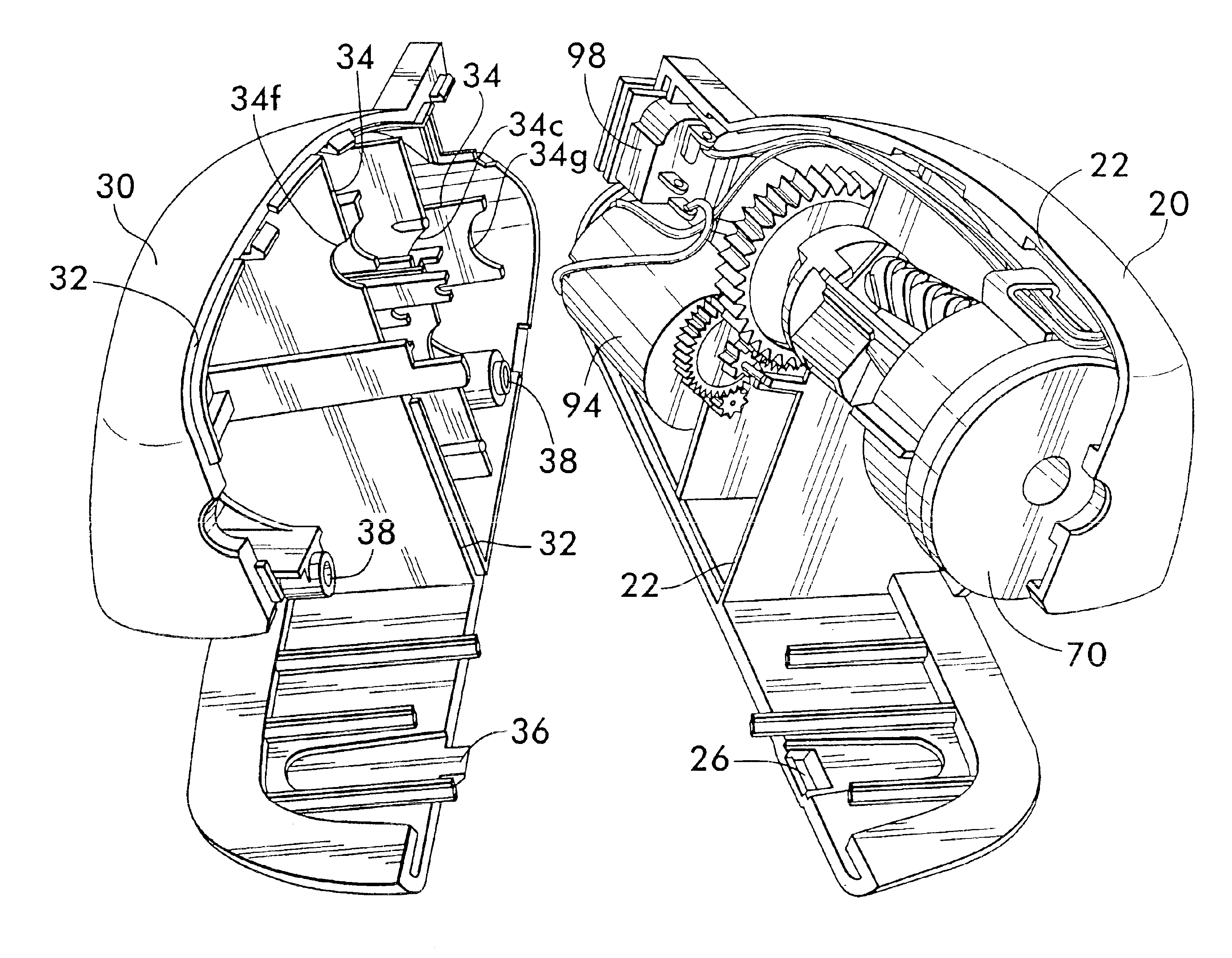
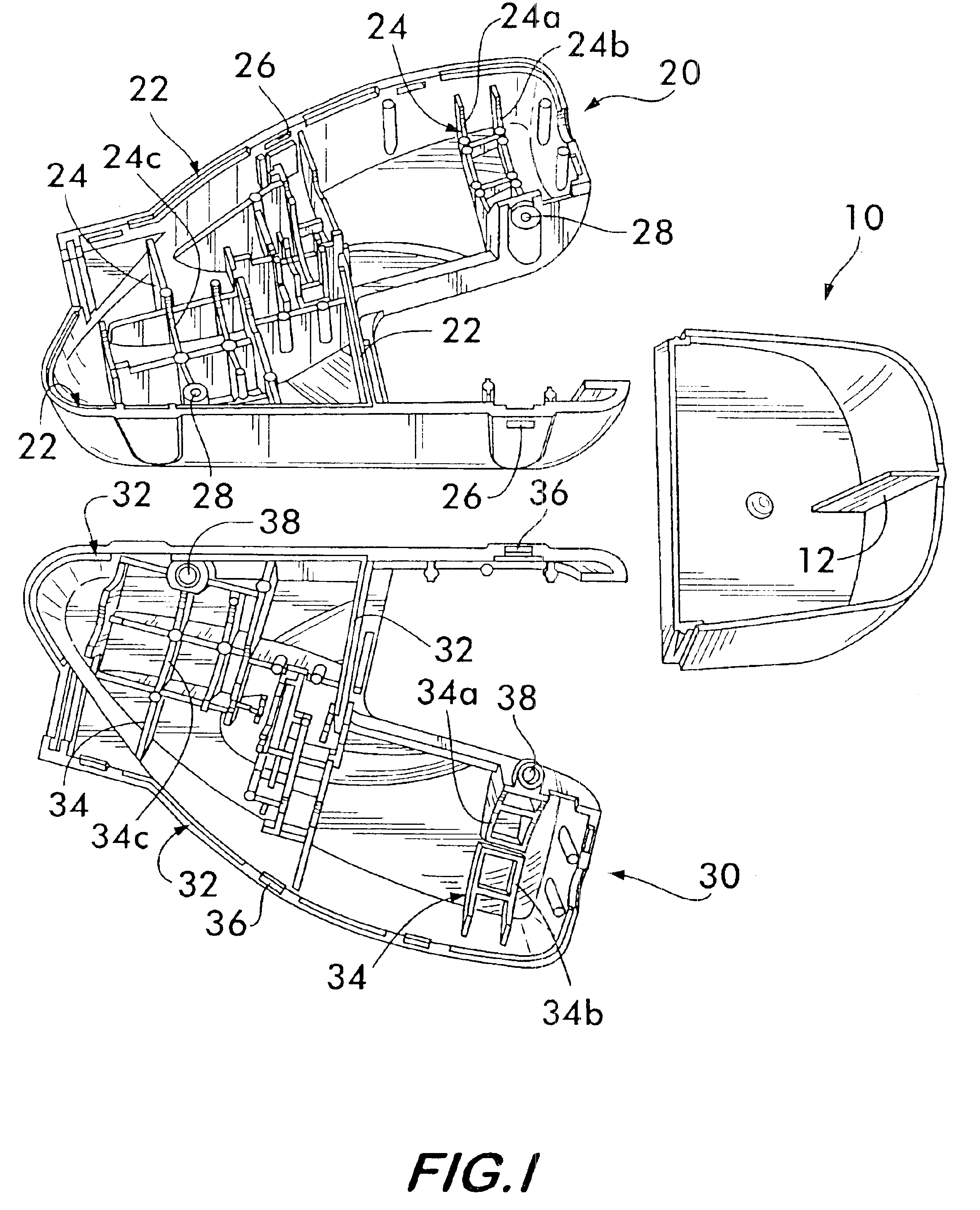
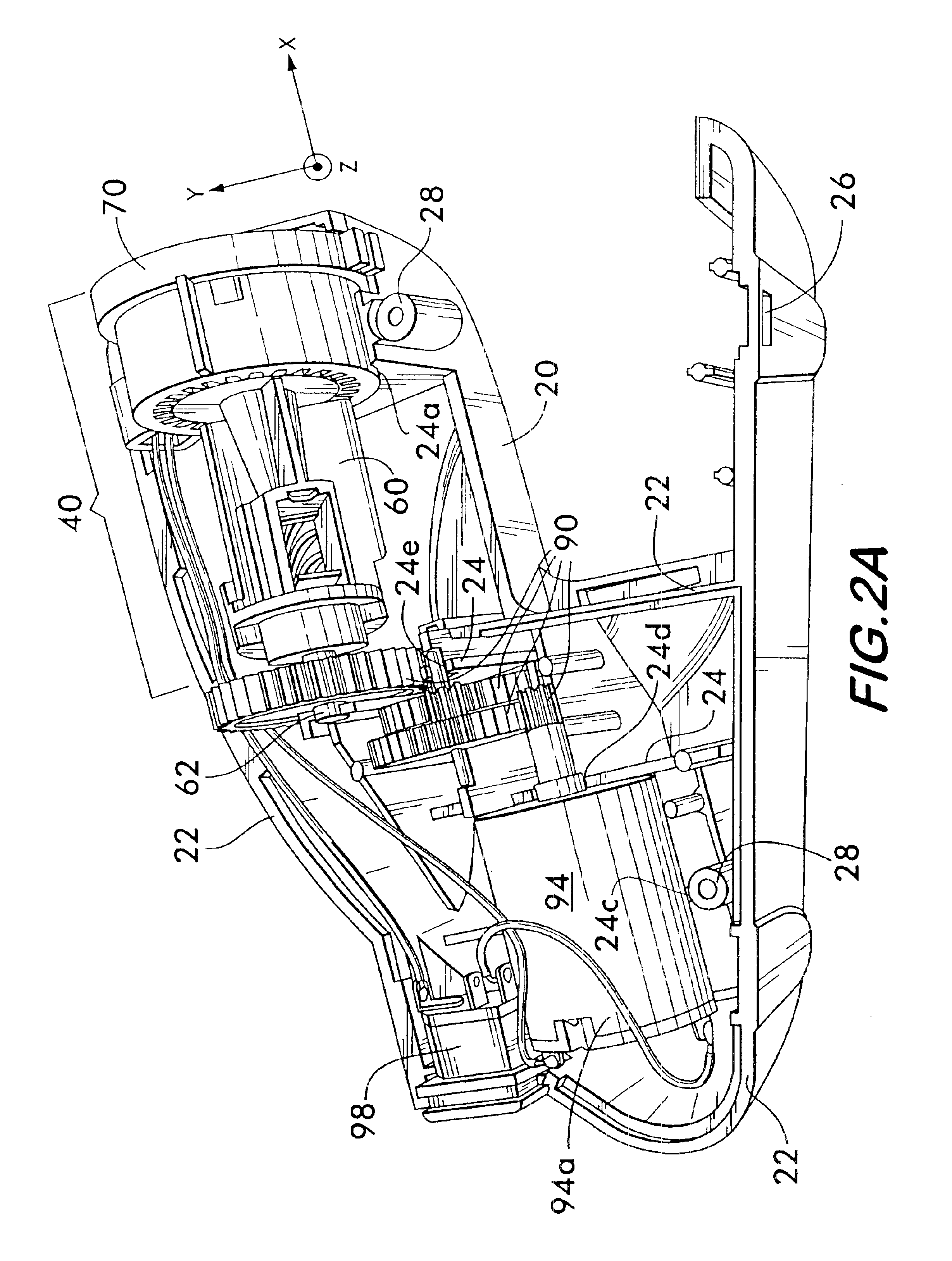
[0019]FIG. 1 is a perspective view of first and second external shells 20, 30 which can be mated to form the housing 21 of the pencil sharpener 100 shown in FIG. 6. A receptacle 10 is configured to be removably matable with the first and second external shells 20, 30 for receiving pencil shavings discharged from a sharpening sub-assembly of the pencil sharpener. As shown in FIG. 1, first external shell 20 has internal ribs 24 defining a first plurality of support surfaces, e.g. 24a, 24b, 24c. The support surfaces can be a semi-circle, a semi-square, a semi-rectangle, or other open shape, as discussed below. Similarly, the second external shell 30 has internal ribs 34 defining a second plurality of support surfaces, e.g. 34a, 34b, 34c. The first and second pluralities of support surfaces are complementary in that they cooperate to fixedly retain the internal components in a predefined x, y, z spatial relationship when the external shells 20, 30 are mated.

[0020]The second external she...


PUM


Abstract

A pencil sharpener having a sharpening sub-assembly for sharpening pencils, and first and second external shells having internal ribs defining surfaces for supporting the sharpening sub-assembly. Components of the sub-assembly are placed into corresponding portions defined by the internal ribs. The ribs ensure proper alignment of the components relative to the shell and each other, e.g. in the x- and y-directions. All components may be placed in the shell in a single direction, e.g. in a single axial direction (the z-direction). The components of the pencil sharpener are mounted in place upon fastening together of the first and second external shells. No internal or additional fasteners are required. The sharpening sub-assembly may include an electric motor, a gear assembly, and a cutter assembly including a cutter gear module having an annular ring gear, acting as a carrier support, and housing a pencil insertion switch and/or a receptacle presence switch.

Description

FIELD OF THE INVENTION[0001]The present invention relates generally to pencil sharpeners. More particularly, the present invention relates to an electric pencil sharpener having an internal structure which simplifies assembly and provides a corresponding reduction in production costs.BACKGROUND OF THE INVENTION[0002]Typical electric pencil sharpeners include an electric motor, a speed reducing gear train, a multi-piece cutter assembly, a pencil size selector guide and / or a pencil alignment device, and a switch for activating the motor, e.g. upon insertion of a pencil. A removable receptacle may also be provided for collecting shavings with some pencil sharpeners. These sharpeners may include a receptacle presence switch for preventing operation of the motor unless the removable receptacle is fitted to the housing.[0003]Many of the above components e.g, the motor, gear train and cutter assembly are mounted on various internal support structures within the housing to permit precise al...

Claims


Application Information

Patent Timeline
Patent Type & Authority Patents(United States)
IPC IPC(8): B43L23/02B43L23/00
CPCB43L23/02
Inventor RICONO, THOMAS R.PARRISH, MICHAEL LEEDALEY, JR., PHILLIP BRUCEDALEY, SALLIE S.
Owner SANFORD LP
Why Eureka
Try Eureka