Lubrication system valve

a technology of lubrication system and valve body, which is applied in the direction of mechanical equipment, machines/engines, transportation and packaging, etc., can solve the problems of long and complex scavenging pump, requiring many bearings, shafts, seals, couplings,

Inactive Publication Date: 2005-05-03
HAMILTON SUNDSTRAND CORP
View PDF11 Cites 13 Cited by
  • Summary
  • Abstract
  • Description
  • Claims
  • Application Information

AI Technical Summary

Problems solved by technology

This leads to a scavenge pump which is overly long and complex requiring many bearings, shafts, seals, and couplings.

Method used


Image

  • Lubrication system valve
  • Lubrication system valve
  • Lubrication system valve

Examples


Embodiment Construction

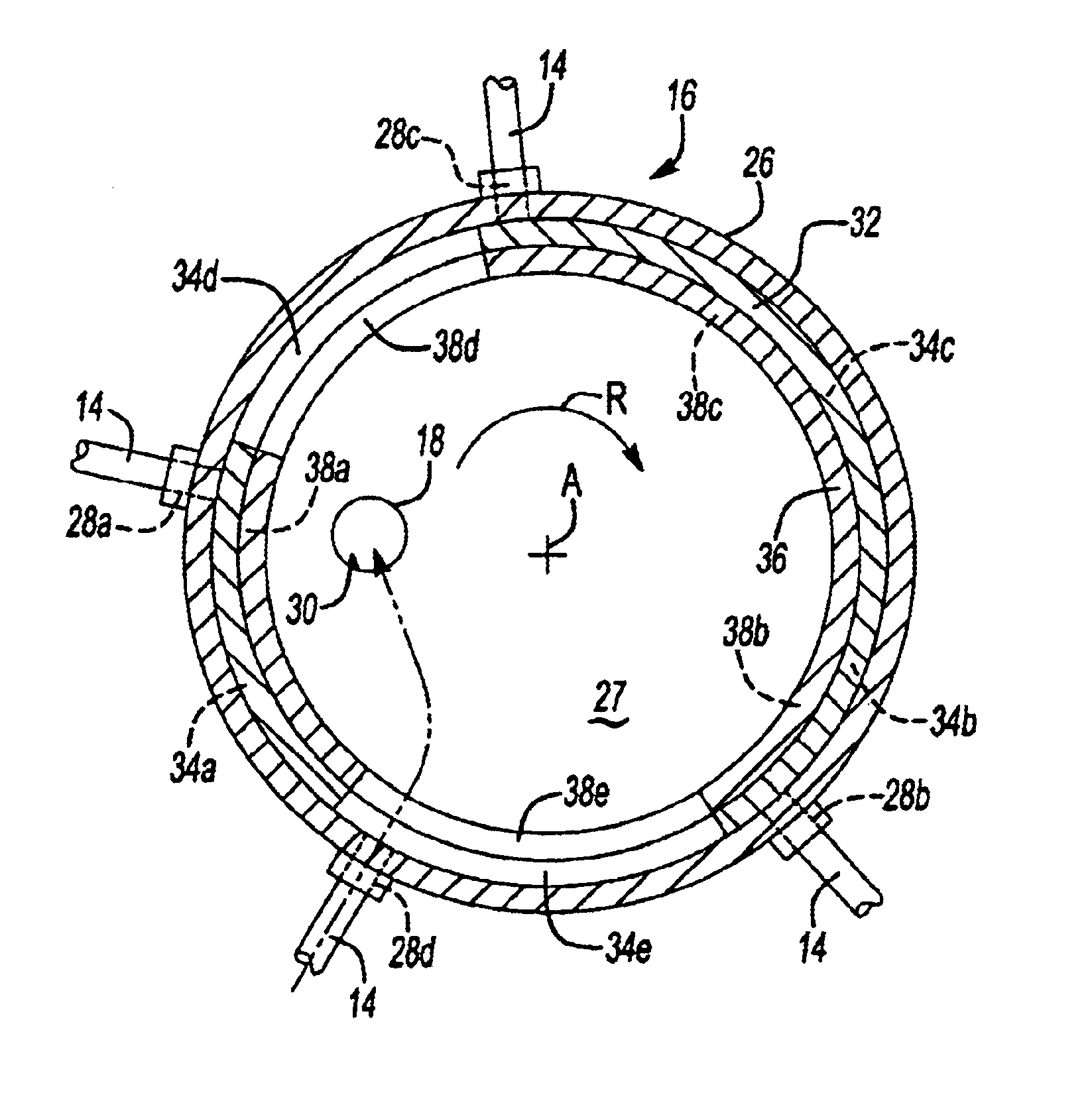
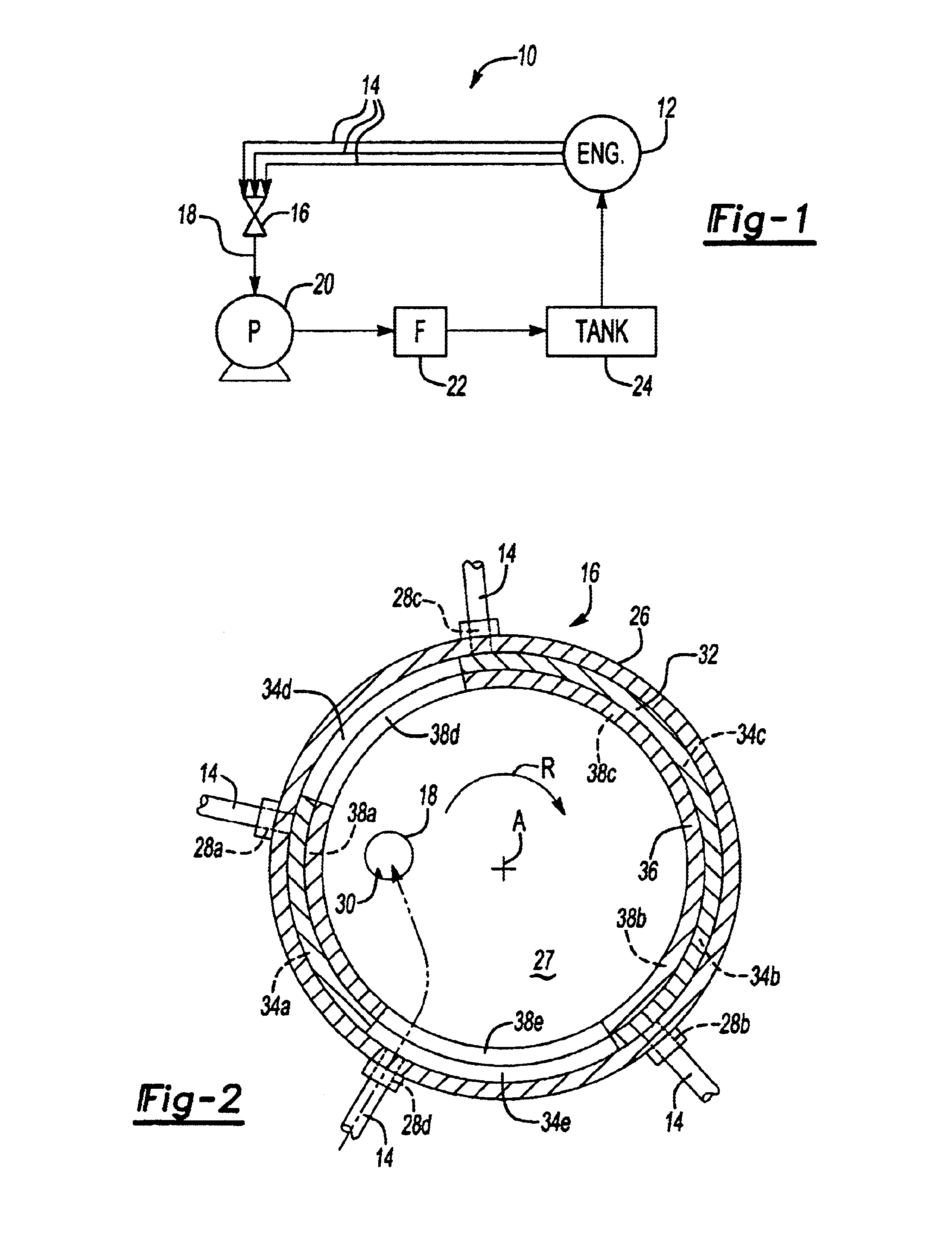
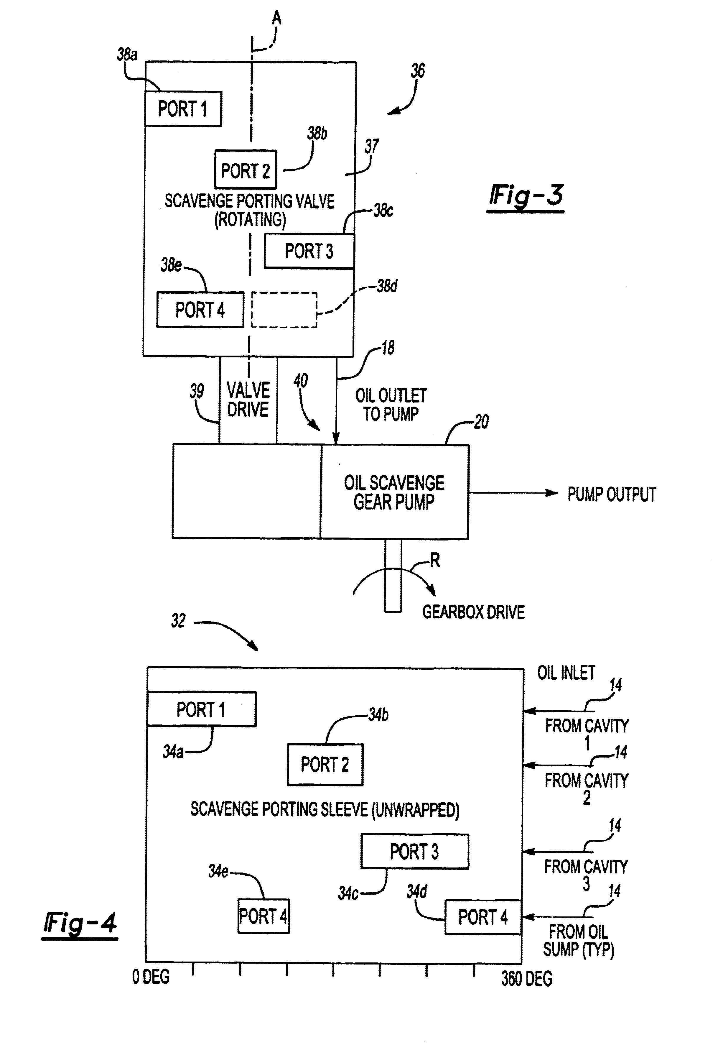
[0011]A fluid scavenging system 10 is schematically depicted in FIG. 1 and represents a portion of a lubrication system. The system 10 includes a machine such as a gas turbine engine 12 having a plurality of fluid compartments such as bearing compartments that receive lubrication. These bearing compartments must be scavenged to ensure that all the bearing oil is removed to maintain desired operation of the engine 12. To this end, fluid conduits 14 are in fluid communication with each of the bearing compartments and are connected to a pump to pump the oil from the bearing compartments. Normally, the fluid conduits are respectively connected to a separate set of pump elements each of which separately pumps the bearing compartment. The present invention utilizes a valve 16 arranged between the fluid conduits 14 and the pump 20 to scavenge the oil from all of the bearing compartments using a single set of pump elements. The valve 16 includes a common fluid outlet 18 fluidly connected to...


PUM


Abstract

A fluid scavenging system is provided for a lubrication system including a gas turbine engine having bearing compartments. A valve includes a housing with an outlet and a plurality of fluid inlets respectively in fluid communication with the bearing compartments. The valve includes a rotationally driven member arranged within the housing with the member having a plurality of ports arranged thereon each defining an arcuate slot. Each of the ports are selectively in fluid communication with one of the fluid inlets through the arcuate slot during rotation of the member for selectively permitting fluid flow between the opening of one of the fluid inlets through one of the corresponding ports in the member. A fluid pump is fluidly connected to the outlet for drawing fluid from each of the plurality of fluid compartments during fluid rotation of the member. The driven member rotates about an axis 360°, and preferably, the ports are respectively aligned with the fluid inlets for approximately at least 360° such that the pump does not run dry. The arcuate slots may overlap during a range of degrees such that more than one compartment is scavenged. The size of the arcuate slot and degrees through which the arcuate slot is in communication with its respective inlet determines the duration that a particular bearing compartment is scavenged and the volume of bearing fluid that may be removed from the compartment.

Description

BACKGROUND OF THE INVENTION[0001]This invention relates to a lubrication system, and more particularly, the invention relates to a valve used for scavenging lubricating fluid from separate compartments of a machine.[0002]Gas turbine engines and other rotating machines typically have several bearing areas that must be lubricated and scavenged. On complex multi-shaft engines the number of individual bearing compartments can be as high as ten or more. Each bearing cavity must be scavenged separately to ensure that spent bearing oil is properly returned to the tank for reuse and not allowed to leak in the gas path of the engine where it may ignite.[0003]A pump is used to scavenge the bearing cavities to remove the bearing oil. In the prior art, scavenging is typically accomplished by using separate scavenge pump elements for each compartment. That is, each bearing compartment has its own set of pump elements such that for complex multi-shaft engines there may be as many as ten or more s...

Claims


Application Information

Patent Timeline
Patent Type & Authority Patents(United States)
IPC IPC(8): F16K11/076F16K11/06
CPCF16K11/076Y10T137/86863
Inventor PARSONS, DOUGLAS A.MARKS, KENNETH
Owner HAMILTON SUNDSTRAND CORP
Why Eureka
Try Eureka