Drip irrigation hose and method and apparatus for making same

a technology of drip irrigation and hoses, which is applied in the direction of watering devices, other domestic objects, coatings, etc., can solve the problems of high water resource conservativeness, sensitivity to clogging, and difficulty in ensuring relatively uniform discharge rates along the length of the hose, so as to reduce clogging sensitivity, reduce clogging, and produce in volume

Inactive Publication Date: 2005-05-03
COHEN
View PDF18 Cites 56 Cited by
  • Summary
  • Abstract
  • Description
  • Claims
  • Application Information

AI Technical Summary

Benefits of technology

[0008]An object of the present invention is to provide a drip irrigation hose in which the discharge rate from each emitter element is less sensitive to changes in the pressure of the water within the hose at the respective emitter element. Another object of the invention is provide a drip irrigation hose which has less sensitivity to clogging, and which more conveniently permits clogging particles to be dislodged. A further object of the invention is to provide a drip irrigation hose of a construction which can be produced in volume and at relatively low cost. Still further objects of the invention are to provide a method and apparatus of making such drip irrigation hoses.
[0016]In some embodiments described below, the relatively elastic material is a thermoplastic elastomer. Other embodiments are described wherein the relatively elastic material is made of two liquid materials which, when mixed together and heated, cross-link to produce a relatively elastic solid material. A further embodiment is described wherein the tube includes an adhesive coating on its inner surface to promote the adhesion of the emitter elements thereto and also to strengthen the tube particularly at the outlet openings.
[0018]As will be described more particularly below, a drip irrigation hose constructed in accordance with the foregoing features provides pressure compensation in the water discharge rate from each emitter element, thereby making the discharge from each emitter element less sensitive to changes in the pressure of the water within the hose at the respective emitter element. Certain embodiments of the invention produce not only compressional forces in the emitter elements, but also tangential forces which tend to dislodge clogging particles, thereby lowering the sensititivity to clogging. Many of the foregoing features also enable such drip irrigation hoses to be made in volume and at relatively low cost.

Problems solved by technology

Drip irrigation hoses are increasingly being used for irrigating various types of plants since they supply the water directly to the root regions of the plants, and therefore are highly conservative of water resources.
One problem in using drip irrigation hoses is the difficulty in ensuring relatively uniform discharge rates along the length of the hose.
This problem is particularly acute where extremely long lengths of the hose are used since the hose itself produces a pressure drop along its length tending to decrease the discharge rate of the emitters at the end of the hose.
This sensitivity of the discharge rate to the water pressure is also a problem where the land being irrigated is not flat and even.
Another problem with such drip irrigation hoses is sensitivity to clogging, and the difficulty in dislodging clogging particles.
Accordingly, the cost involved in producing such drip irrigation hoses is a significant factor in their use.

Method used


Image

  • Drip irrigation hose and method and apparatus for making same
  • Drip irrigation hose and method and apparatus for making same
  • Drip irrigation hose and method and apparatus for making same

Examples


Embodiment Construction

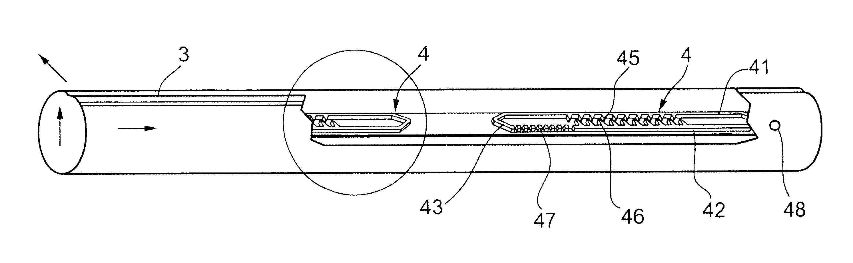
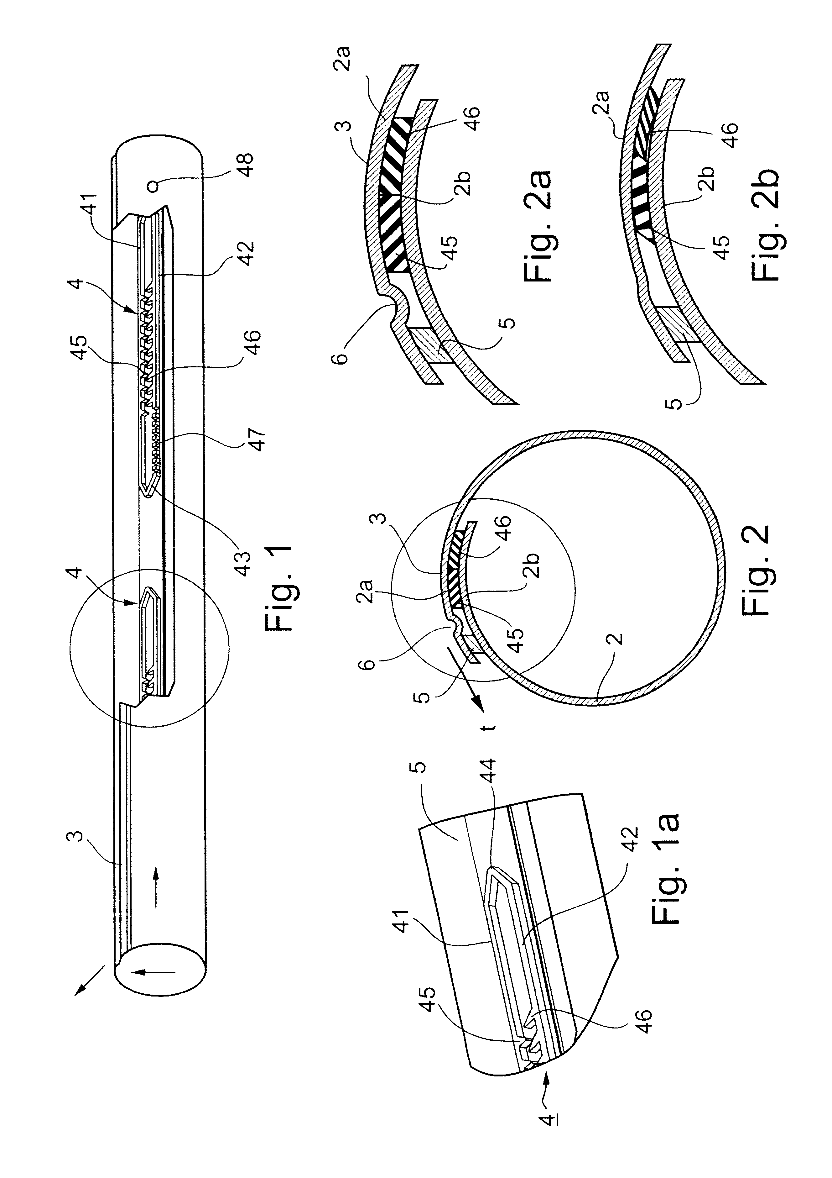
[0067]With reference to FIGS. 1 and 2, there is illustrated a drip irrigation hose comprising a sheet 2 of thin, flexible plastic material having opposed outer edge portions 2a, 2b which are overlapped and bonded together to form a seam 3 extending longitudinally of the so-produced tube for conducting pressurized water therethrough. A plurality of emitter elements, each generally designated 4, are bonded to and between the overlapping portions 2a, 2b of the sheet 2 at longitudinally-spaced locations along the seam 3, and define a plurality of restricted flow passageways for discharging water from outlets in the seamed hose at a slow rate.

[0068]The overlapping portions 2a, 2b of the flexible sheet are bonded together both by the emitter elements 4, and by a continuous, longitudinally-extending rib 5 extending along the outer edge of the outer overlapping portion 2a. As shown particularly in FIGS. 2 and 2a, the outer overlapping portion 2a is formed with an inwardly-extending slack 6 ...


PUM

PropertyMeasurementUnit
temperatureaaaaaaaaaa
timeaaaaaaaaaa

Abstract

A drip irrigation hose formed with a plurality of outlets for discharging the water at longitudinally-spaced locations along the length of the hose includes a plurality of emitter elements secured to the hose at longitudinally-spaced locations along its length to define a plurality of turbulent flow passageways each in communication with the interior of the hose for discharging water from a hose outlet at a slow rate. Each of the turbulent flow passageways is defined by a relatively elastic first material co-extruded with a relatively inelastic second material both bonded to the hose with the relatively elastic material being pressure-deformable, as compared to the relatively inelastic material, to change the turbulent flow passageway of each emitter element in response to the pressure of the water in the hose at the respective emitter element.

Description

RELATED APPLICATIONS[0001]The present application is a continuation-in-part of International Patent Application PCT / IL01 / 00751, filed Aug. 13, 2001, published Feb. 28, 2002 as International Publication No. WO 02 / 15670 A2, which is a continuation-in-part, and claiming the priority date of, U.S. application Ser. No. 09 / 639,768 filed Aug. 21, 2000 and issued as U.S. Pat. No. 6,371,390 on Apr. 16, 2002. The present application also includes subject matter of U.S. Provisional Application 60 / 332,568, filed Nov. 26, 2001, the priority of date which is also herein claimed, and the contents of which are incorporated herein by reference.FIELD AND BACKGROUND OF THE INVENTION[0002]The present invention relates to drip irrigation hoses, and to methods and apparatus for making such hoses.[0003]Drip irrigation hoses are increasingly being used for irrigating various types of plants since they supply the water directly to the root regions of the plants, and therefore are highly conservative of wate...

Claims


Application Information

Patent Timeline
Patent Type & Authority Patents(United States)
IPC IPC(8): A01G25/02B29C47/00B29C47/02B29C59/04B29C48/07B29C48/157
CPCA01G25/02A01G25/023B29C47/0004B29C47/0019B29C47/028A01G25/026Y10T156/1013B29K2301/10B29L2023/22B29L2031/7004B29C59/043B29C48/022B29C48/07B29C48/157Y02A40/22
Inventor COHEN
Owner COHEN
Why Eureka
Try Eureka