Drip irrigation hose and method and apparatus for making same

Inactive Publication Date: 2003-03-27
COHEN
View PDF0 Cites 55 Cited by
  • Summary
  • Abstract
  • Description
  • Claims
  • Application Information

AI Technical Summary

Benefits of technology

0008] An object of the present invention is to provide a drip irrigation hose in which the discharge rate from each emitter element is less sensitive to changes in the pressure of the water within the hose at the respective emitter element. Another object of the invention is provide a drip irrigation hose which has less sensitivity to clog

Problems solved by technology

Drip irrigation hoses are increasingly being used for irrigating various types of plants since they supply the water directly to the root regions of the plants, and therefore are highly conservative of water resources.
One problem in using drip irrigation hoses is the difficulty in ensuring relatively uniform discharge rates along the length of the hose.
This problem is particularly acute where extremely long lengths of the hose are used since the hose itself produces a p

Method used


Image

  • Drip irrigation hose and method and apparatus for making same
  • Drip irrigation hose and method and apparatus for making same
  • Drip irrigation hose and method and apparatus for making same

Examples


Embodiment Construction

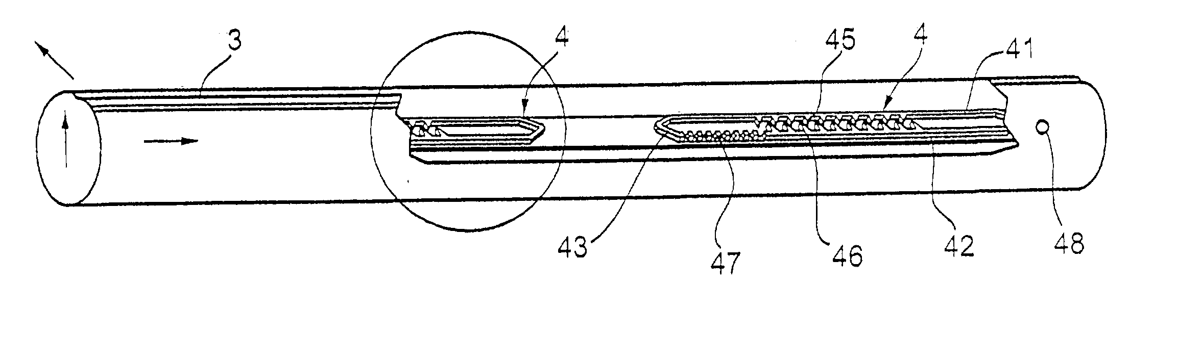
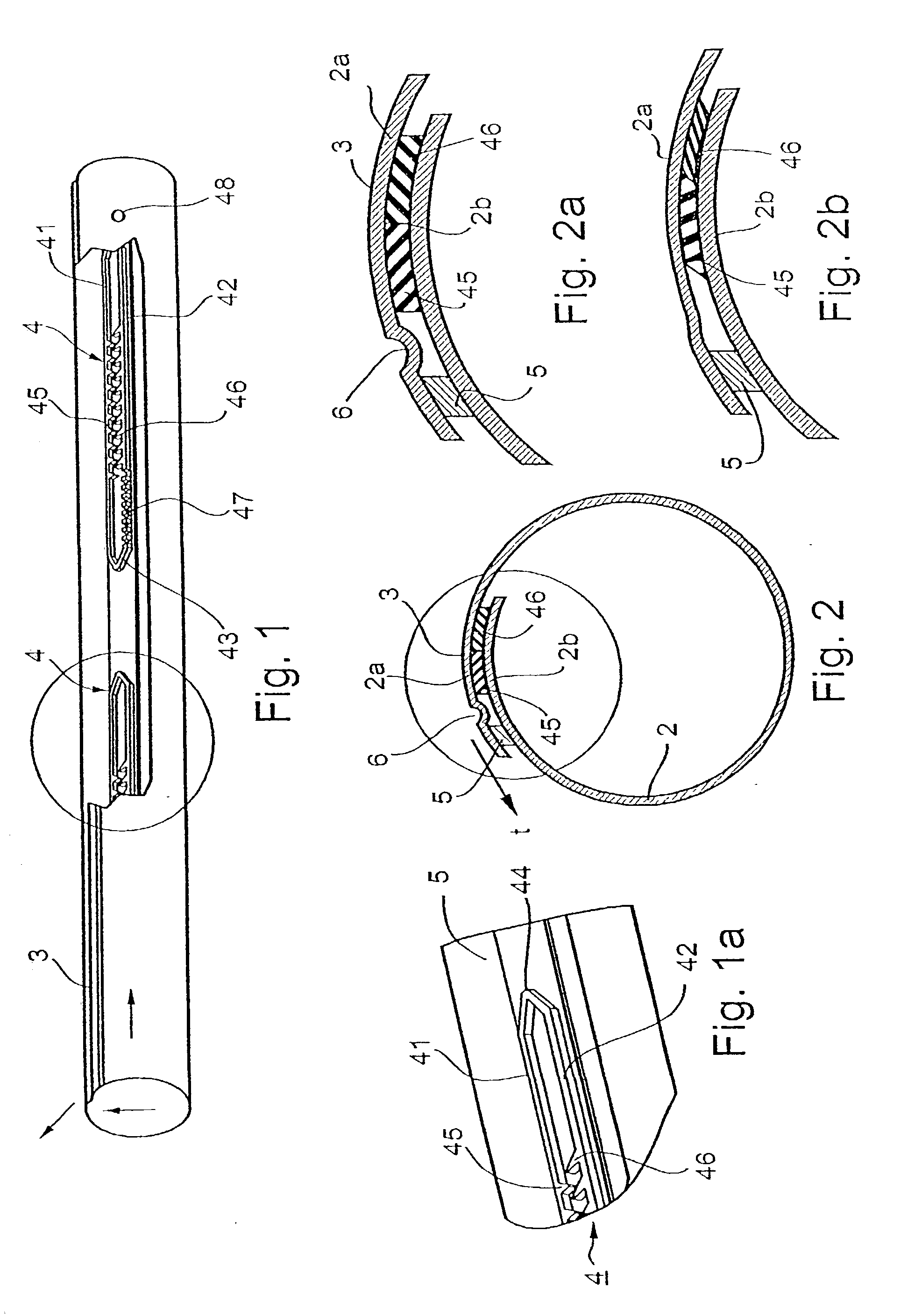
[0067] With reference to FIGS. 1 and 2, there is illustrated a drip irrigation hose comprising a sheet 2 of thin, flexible plastic material having opposed outer edge portions 2a, 2b which are overlapped and bonded together to form a seam 3 extending longitudinally of the so-produced tube for conducting pressurized water therethrough. A plurality of emitter elements, each generally designated 4, are bonded to and between the overlapping portions 2a, 2b of the sheet 2 at longitudinally-spaced locations along the seam 3, and define a plurality of restricted flow passageways for discharging water from outlets in the seamed hose at a slow rate.

[0068] The overlapping portions 2a, 2b of the flexible sheet are bonded together both by the emitter elements 4, and by a continuous, longitudinally-extending rib 5 extending along the outer edge of the outer overlapping portion 2a. As shown particularly in FIGS. 2 and 2a, the outer overlapping portion 2a is formed with an inwardly-extending slack ...


PUM

PropertyMeasurementUnit
Lengthaaaaaaaaaa
Timeaaaaaaaaaa
Pressureaaaaaaaaaa

Abstract

A drip irrigation hose formed with a plurality of outlets for discharging the water at longitudinally-spaced locations along the length of the hose includes a plurality of emitter elements secured to the hose at longitudinally-spaced locations along its length to define a plurality of turbulent flow passageways each in communication with the interior of the hose for discharging water from a hose outlet at a slow rate. Each of the turbulent flow passageways is defined by a relatively elastic first material co-extruded with a relatively inelastic second material both bonded to the hose with the relatively elastic material being pressure-deformable, as compared to the relatively inelastic material, to change the turbulent flow passageway of each emitter element in response to the pressure of the water in the hose at the respective emitter element.

Description

[0001] The present application is the U.S. National Entry Phase of International Patent Application PCT / IL01 / 00751, filed Aug. 13, 2001, published Feb. 28, 2002 as International Publication No. WO 02 / 15670 A2, based on, and claiming the priority date of, U.S. application Ser. No. 09 / 639,768 filed Aug. 21, 2000 and issued as U.S. Pat. No. 6,371,390 on Apr. 16, 2002. The present application also includes subject matter of U.S. Provisional Application No. 60 / 332,568, filed Nov. 26, 2001, the priority of date which is also herein claimed, and the contents of which are incorporated herein by reference.FIELD AND BACKGROUND OF THE INVENTION[0002] The present invention relates to drip irrigation hoses, and to methods and apparatus for making such hoses.[0003] Drip irrigation hoses are increasingly being used for irrigating various types of plants since they supply the water directly to the root regions of the plants, and therefore are highly conservative of water resources. One type of irri...

Claims


Application Information

Patent Timeline
IPC IPC(8): A01G25/02B29C48/07B29C48/157B29C59/04
CPCA01G25/02A01G25/023B29C47/0004B29C47/0019B29C47/028Y10T156/1013B29K2301/10B29L2023/22B29L2031/7004A01G25/026B29C59/043B29C48/022B29C48/07B29C48/157Y02A40/22
Inventor COHEN
Owner COHEN
Why Eureka
Try Eureka