High-resolution projection display system

a projection display and high-resolution technology, applied in the field of image display systems, can solve the problems of unsuitable resolution for large-format displays, adversely affecting yield-per-wafer and cost, and achieve the effect of enhancing the resolution of the display image and compact projection system

Inactive Publication Date: 2005-05-03
VIAVI SOLUTIONS INC
View PDF14 Cites 35 Cited by
  • Summary
  • Abstract
  • Description
  • Claims
  • Application Information

AI Technical Summary

Benefits of technology

[0008]The present invention enables high-resolution image display systems. In some embodiments, a single lamp is used. The lamp output is homogenized in a light integrator, which provides a homogenized light output. The homogenized light output is split into first and second light beams with a beam splitter. A first imager optically coupled to the first light beam produces a first modulated light beam that is optically coupled to first projection optics. The projection optics expand the first modulated light beam to form a first display image portion on a display screen. A second imager optically coupled to the second light beam produces a second modulated light beam that is optically coupled to second projection optics. The second projection optics expand the second modulated light beam to form a second display image portion on the display screen. The first display image portion and the second display image portion are combined at a margin to form a display image. An optional fold mirror(s) is used to enable a more compact projection system.
[0009]In a particular embodiment, the beam splitter is a polarizing beam splitter and the imagers are LCoS SLMs. The first light beam from the polarizing beam splitter has a first polarization state and the second light beam from the polarizing beam splitter has a second polarization state. A half-wave retarder plate in the path of the first light beam rotates the polarization state to operate in conjunction with the LCoS SLM. Thus, the fill output of the lamp is utilized without polarization recovery, and resolution of the display image is enhanced.

Problems solved by technology

However, SLMs suitable for large-format displays might not have suitable resolution for other applications, such as medical imaging, satellite imaging, or other display applications requiring very high information content.
Unfortunately, the resolution acceptable for large-screen displays might not be suitable for high-resolution displays, where the viewer is relatively close to the displayed image and a higher information density is desired.
Unfortunately, both approaches adversely affect yield-per-wafer and cost.
Using multiple SLMs allows the use of slower SLMs to achieve a higher apparent refresh rate, but does not increase the resolution of the display.

Method used


Image

  • High-resolution projection display system
  • High-resolution projection display system
  • High-resolution projection display system

Examples


Embodiment Construction

I. Introduction

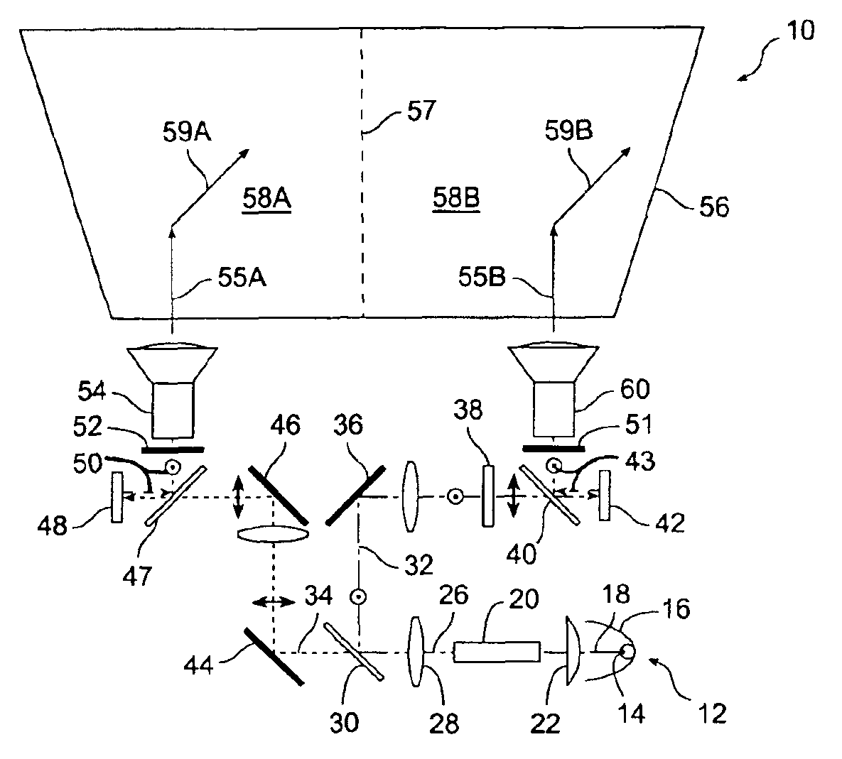
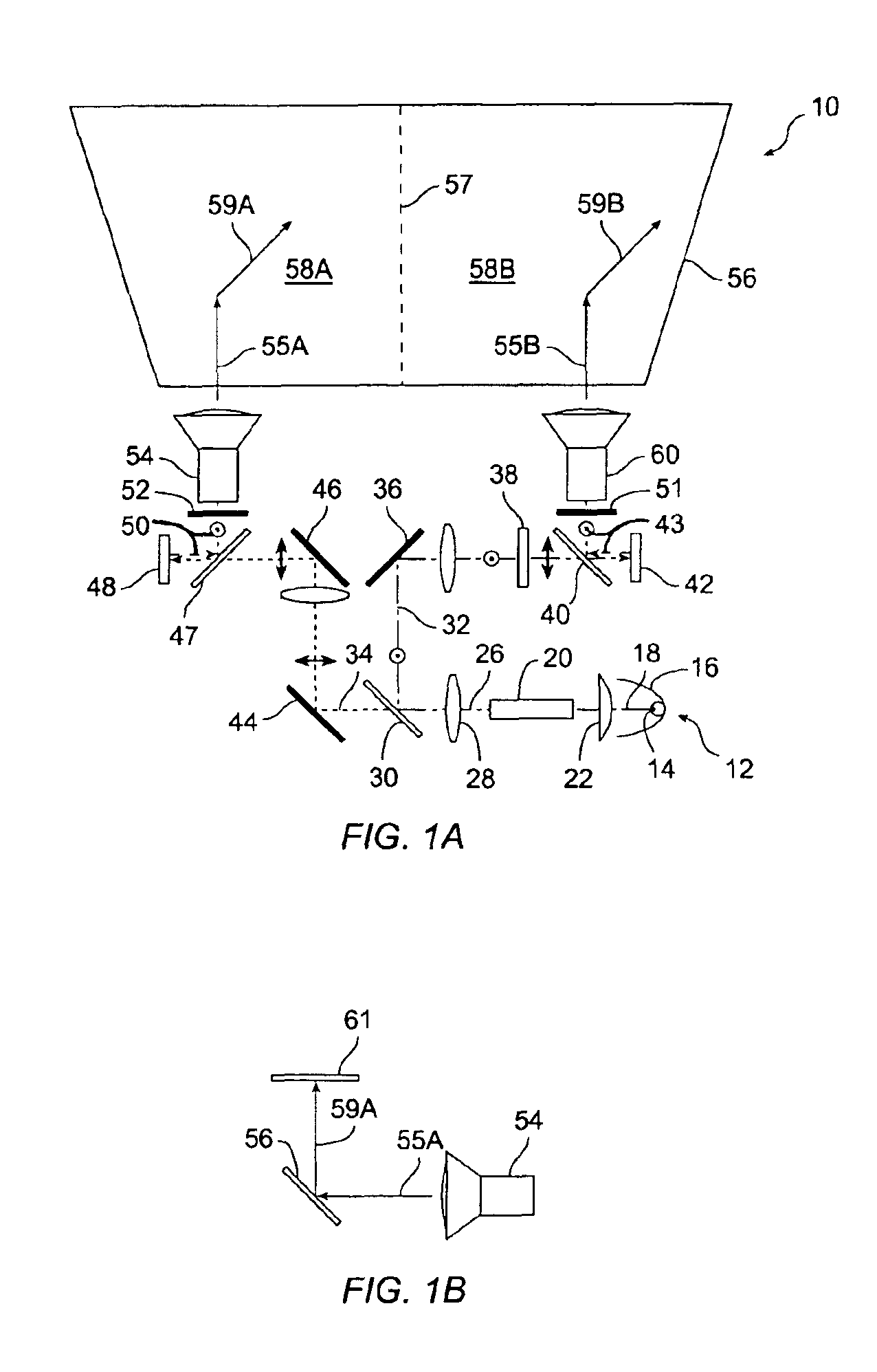
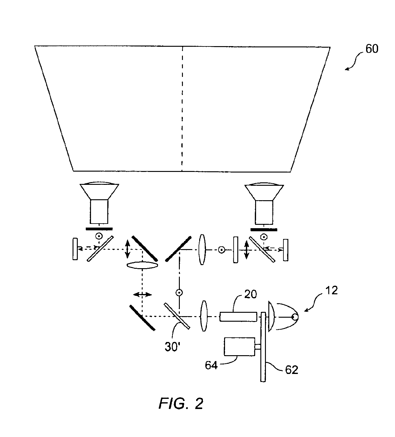
[0014]A projected image is formed from partial images produced by a plurality of SLMs. The modulated light from the each SLM forms a portion of the projected image, and the portions are combined (“stitched”) to form a high-resolution image on a display screen. For example, image portions from two SLMs, each having two million pixels, are stitched together to form a projected image having about four million pixels.

[0015]In one embodiment, liquid-crystal on silicon (“LCoS”) SLMs are used. LCoS SLMs modulate polarized light by reflection. In conventional image display systems, unpolarized light from the lamp is filtered with a pre-polarizer and light having the undesired polarization state is discarded, reducing brightness. Altenatively, light having the undesired polarization state is converted to light of the desired polarization state and is provided to a LCoS SLM. Such techniques are known as polarization conversion / recovery systems, but increase the complexity, cost...


PUM

PropertyMeasurementUnit
optical path lengthaaaaaaaaaa
sizeaaaaaaaaaa
information densityaaaaaaaaaa

Abstract

An image display system uses a polarizing beam splitter to direct light from a lamp to multiple spatial modulators. The spatial light modulators (“SLM”) each generate an image portion, which are stitched together on a display screen to obtain a high resolution image. In particular embodiment, image portions from two conventional SLMs, each controlling about two million pixels, are stitched together to form an image having about four million pixels. In another embodiment, two lamps are used with four SLMs to produce a resultant image having about eight million pixels.

Description

CROSS-REFERENCE TO RELATED APPLICATIONS[0001]Not applicable.STATEMENT REGARDING FEDERALLY SPONSORED RESEARCH OR DEVELOPMENT[0002]Not applicable.REFERENCE TO MICROFICHE APPENDIX[0003]Not applicable.FIELD OF THE INVENTION[0004]This invention relates generally to image display systems, and more particularly to projection display systems using a plurality of spatial light modulators illuminated with light from a lamp, partial images from the spatial light modulators being combined to form a high-resolution image on a display screen.BACKGROUND[0005]Projection display systems use spatial light modulators (“SLMs”) to modulate light from a lamp to produce high-quality images suitable for home theater, large-format front projectors, such as digital cinema, projectors for business conferences, and rear-projection television. The resolution of such systems is related to the number of picture cells (“pixels”) that the SLM generates. The image from the SLM is magnified and projected onto a displ...

Claims


Application Information

Patent Timeline
Patent Type & Authority Patents(United States)
IPC IPC(8): G02B27/10G02F1/00G02F1/1335G02F1/13G03B21/26G03B21/28H04N5/74H04N9/12
CPCG03B21/26H04N9/12H04N5/7441
Inventor GREENBERG, MICHAEL R.BELLIS, MATTHEW W.
Owner VIAVI SOLUTIONS INC
Why Eureka
Try Eureka