Power attenuator with coupling port

a technology of power attenuator and coupling port, which is applied in the direction of coupling device, waveguide type device, line-transmission details, etc., can solve the problem of no built-in device to monitor the input of the power attenuator

Active Publication Date: 2005-05-03
ALCATEL-LUCENT USA INC +1
View PDF4 Cites 4 Cited by
  • Summary
  • Abstract
  • Description
  • Claims
  • Application Information

AI Technical Summary

Benefits of technology

[0002]Exemplary embodiments of the present invention provide a power attenuator with at least one coupling port. The coupling port may be provided to monitor input power levels, output power levels, or other performance operations of the power attenuator. One or more coupling ports may be located on the power attenuator input part to m...

Problems solved by technology

Power attenuators are known, however, there is no built-in device to monitor the input to a pow...

Method used


Image

  • Power attenuator with coupling port
  • Power attenuator with coupling port
  • Power attenuator with coupling port

Examples


Embodiment Construction

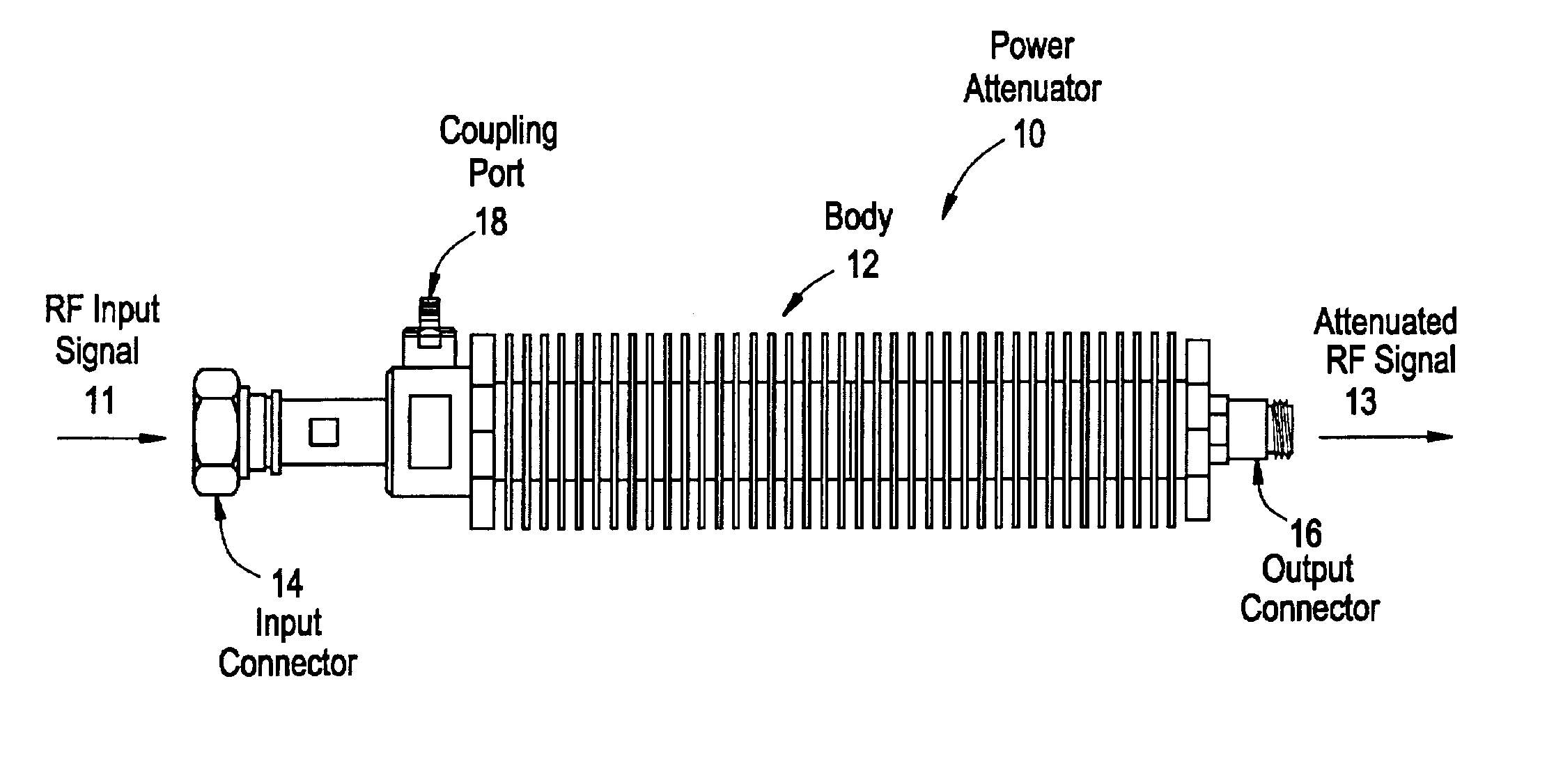
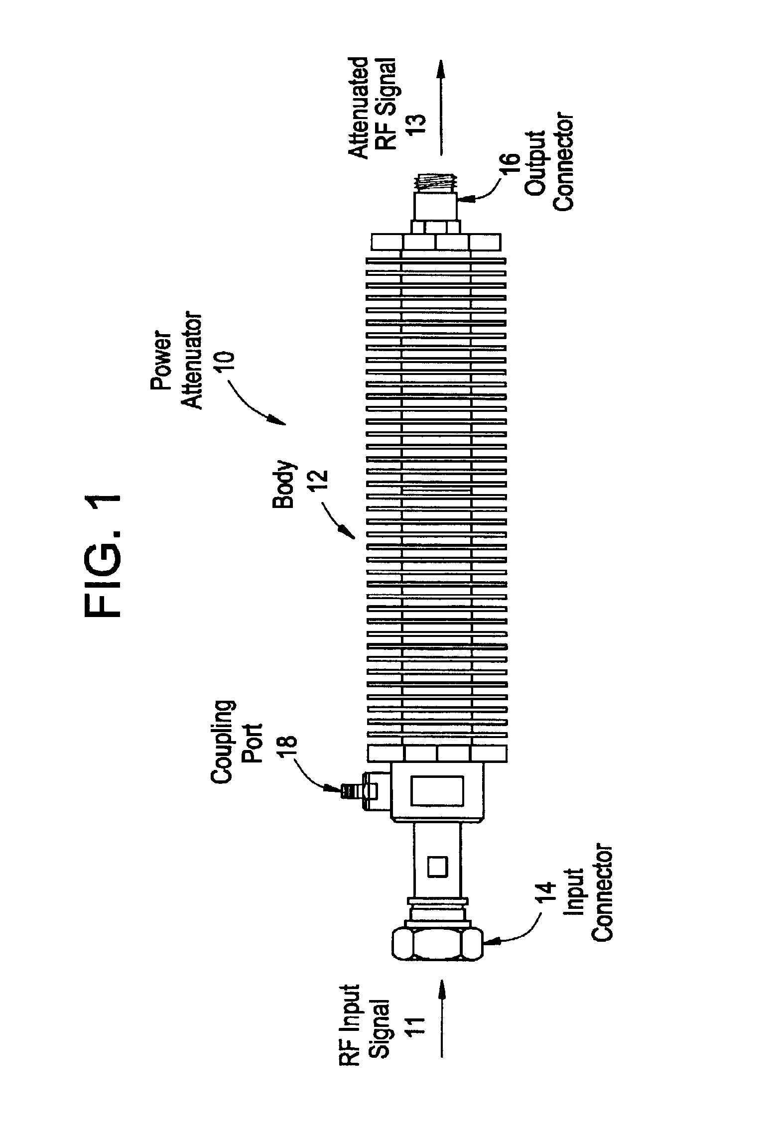
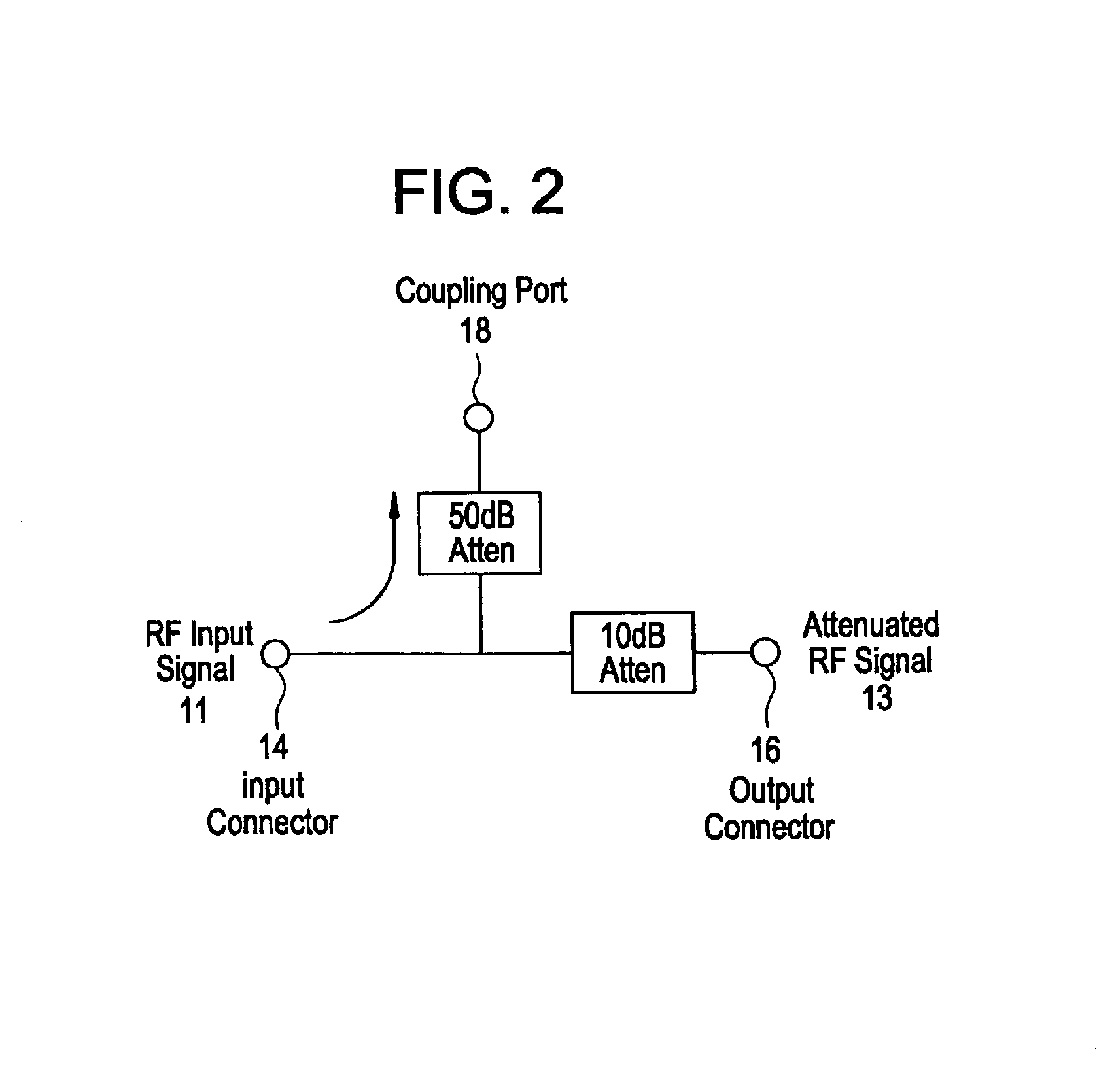
[0007]The present invention, in its exemplary embodiment is directed to a power attenuator 10 with at least one coupling port. FIG. 1 illustrates an exemplary embodiment of the present invention. As shown in FIG. 1, a power attenuator 10 includes a body 12, at least one input connector 14, at least one output connector 16, and at least one coupling port 18. As shown in FIG. 1, the coupling port 18 is provided at the input end of the power attenuator 10, and therefore permits the monitoring of input power levels into the power attenuator 10. It is noted that another coupling port may be provided at the output end of the power attenuator 10 in order to monitor output power levels. Other exemplary power attenuators of the present invention may include input and output coupling ports. In another exemplary embodiment, the power attenuator of the present invention may include more than one input and / or coupling ports.

[0008]In operation, one or more RF signals 11 are input through the inpu...


PUM


Abstract

A power attenuator with at least one coupling port. The coupling port may be provided to monitor input power levels, out put power levels, or other operations of the power attenuator. One or more coupling ports may be located on the power attenuator input part to monitor input power levels and/or on the power attenuator output part to monitor output power levels. The coupling port(s) may be coupled to the main RF path by resistive coupling or reactive coupling. The coupling port(s) allow monitoring of the RF signal passing through the power attenuator to detect for incipient failures.

Description

BACKGROUND OF THE INVENTION[0001]Power attenuators are known, however, there is no built-in device to monitor the input to a power attenuator, the internal operation of the power attenuator, or the output of the power attenuator.SUMMARY OF THE INVENTION[0002]Exemplary embodiments of the present invention provide a power attenuator with at least one coupling port. The coupling port may be provided to monitor input power levels, output power levels, or other performance operations of the power attenuator. One or more coupling ports may be located on the power attenuator input part to monitor input power levels and / or on the power attenuator output part to monitor output power levels. The coupling port(s) are coupled to the main radio frequency (“RF”) path by resistive coupling or reactive coupling. The coupling port(s) allow monitoring of the RF signal passing through the power attenuator to detect for incipient failures.BRIEF DESCRIPTION OF THE DRAWINGS[0003]Exemplary embodiments of ...

Claims


Application Information

Patent Timeline
IPC IPC(8): H01P1/22
CPCH01P1/22
Inventor JOCHER, RONALD WILLIAM
Owner ALCATEL-LUCENT USA INC
Why Eureka
Try Eureka