Nine-position resistor ladder switch assembly

a resistor and ladder technology, applied in transmission systems, analogue/digital conversion, instruments, etc., can solve problems such as complex problems, fluctuations in battery voltage and voltages appearing at the output of ladder networks, and limited number of resistor ladder switch assemblies

Active Publication Date: 2007-09-13
GM GLOBAL TECH OPERATIONS LLC
View PDF6 Cites 3 Cited by
  • Summary
  • Abstract
  • Description
  • Claims
  • Application Information

AI Technical Summary

Problems solved by technology

For this and other reasons, resistor ladder switch assemblies have been limited in the number of switches that they may employ.
The problem is complicated due to supply voltage (e.g., battery) variations.
Additionally, other operational conditions experienced in the vehicular environment may cause fluctuations in the battery voltage and the voltages appearing at the output of the ladder networks, including extreme temperature variations (e.g., −40 to 80 degrees Celsius), vibrations, and corrosive agents.
The need to utilize separate four-resistor and five-resistor ladder networks providing first and second output voltages, respectively, results in a more complex, costly, and cumbersome system.

Method used


Image

  • Nine-position resistor ladder switch assembly
  • Nine-position resistor ladder switch assembly
  • Nine-position resistor ladder switch assembly

Examples


Embodiment Construction

[0012] The following detailed description of the invention is merely exemplary in nature and is not intended to limit the scope, applicability, or configuration of the invention in any way. Rather, the following description provides a convenient illustration for implementing exemplary embodiments of the invention. Various changes to the described embodiments may be made in the function and arrangement of the elements described herein without departing from the scope of the invention.

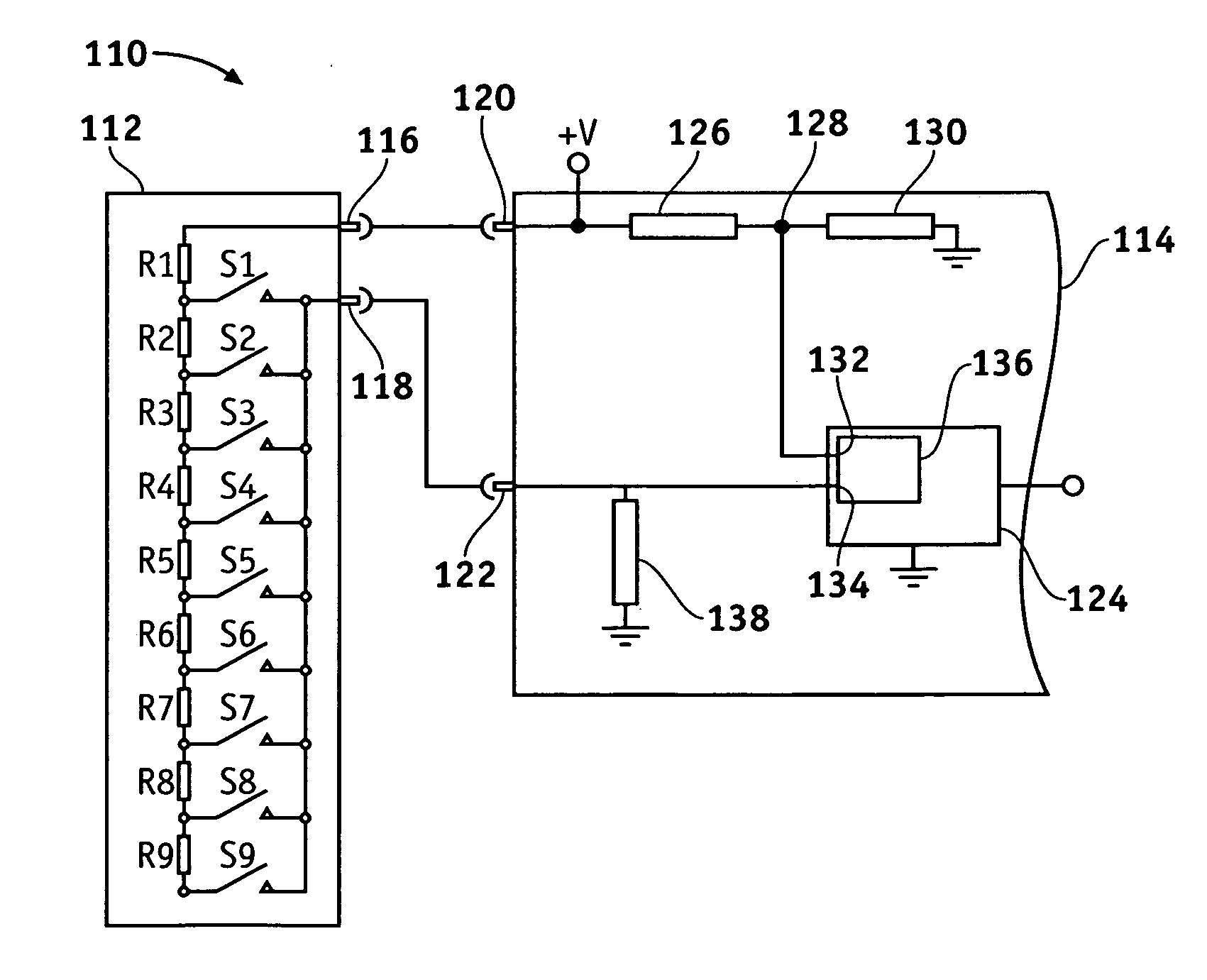
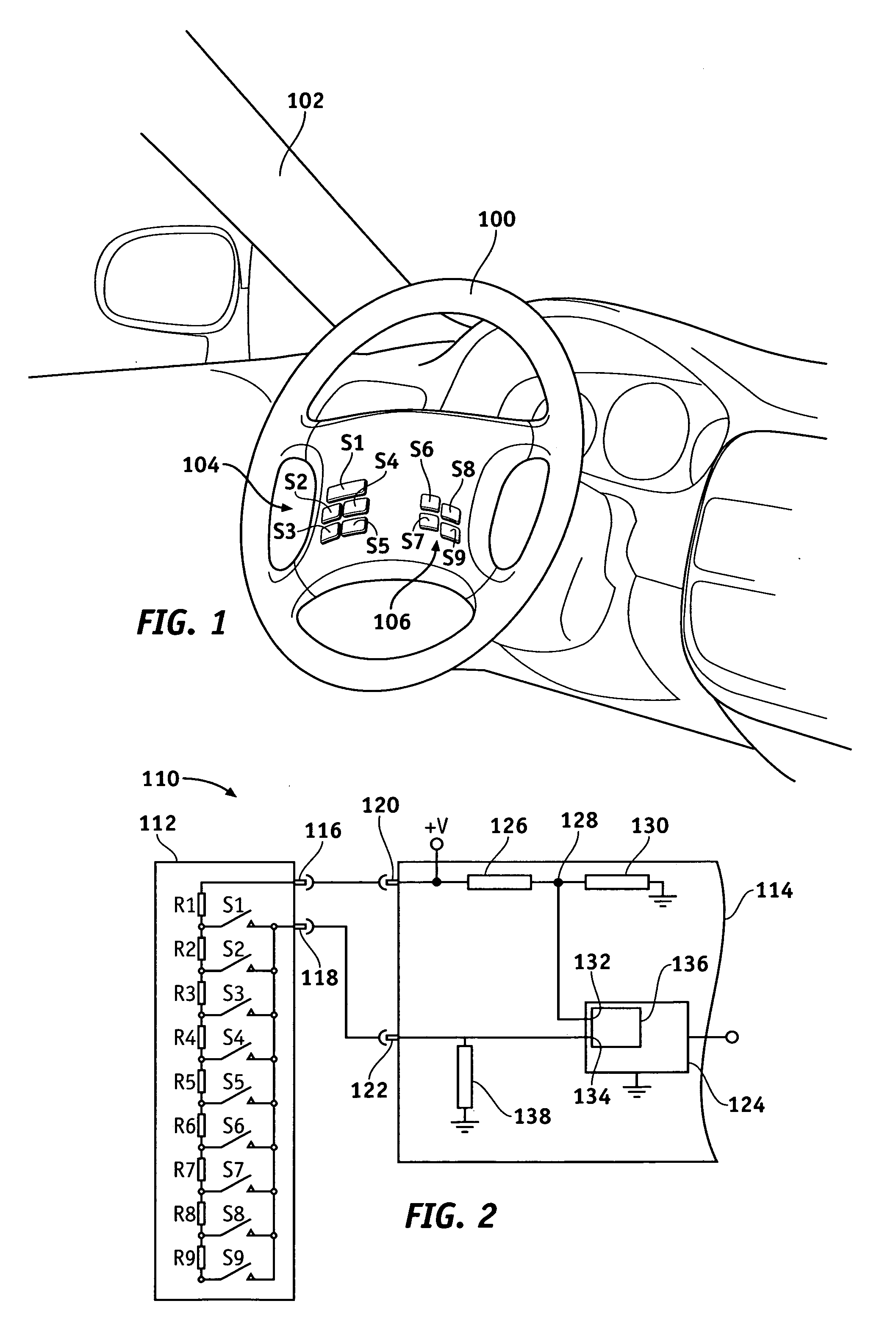
[0013]FIG. 1 is an isometric view of a steering wheel assembly 100 deployed on a vehicle 102. A user interface comprising nine switches S1-S9 is deployed on a portion of steering wheel assembly 100. Switches S1-S9 may be separated into various switch clusters, and each switch cluster may control a different vehicular feature or different aspects of the same vehicular feature. As shown in FIG. 1, for example, switches S1-S5 may be employed in a left hand switch cluster 104 and configured to control the v...


PUM


Abstract

A switch assembly is provided for use on a vehicle having a source of supply voltage. The assembly comprises a switching network having an input terminal configured to be coupled to the supply voltage and an output terminal. The network comprises: (1) nine series-coupled resistors coupled between the input terminal and the output terminal, each resistor having a substantially predetermined resistance; and (2) nine switches each coupled between the input terminal and the output terminal and capable of being opened and closed by an operator of the vehicle. Eight of the switches are each coupled to a different junction of adjacent resistors, and the ninth switch is coupled between the output terminal and the ninth resistor. The switch assembly further comprises a control module coupled to the output terminal for determining which, if any, of the nine switches is closed.

Description

TECHNICAL FIELD [0001] The present invention relates generally to resistor ladder networks and, more specifically, to a nine-position resistor ladder circuit for use in a vehicular switch assembly. BACKGROUND OF THE INVENTION [0002] As vehicles have developed over the years, the number of vehicular features and the ways in which those features may be adjusted (e.g., the number of feature modes) have increased dramatically. It is now common to provide a group of buttons or switches that a user (e.g., a driver) may utilize to adjust a vehicle's features to a preferential mode, and it is known to use resistor ladder networks in conjunction with these switches. Resistor ladder networks typically comprise a plurality of resistors and a plurality of switches disposed such that the closing of any one of the switches alters either the high resistance or the low resistance of a voltage divider circuit. The voltage divider circuit is comprised of a high resistance between a source of supply v...

Claims


Application Information

Patent Timeline
Patent Type & Authority Applications(United States)
IPC IPC(8): H03M1/12H03M1/78
CPCH03M1/765
Inventor JOHNSON, WADE G.DARIN, MATTHEW A.CIESINSKI, BRIAN J.
Owner GM GLOBAL TECH OPERATIONS LLC
Why Eureka
Try Eureka