Integral eye-path alignment on telephony and computer video devices using a pinhole image sensing device

a technology of image sensing and telephony, applied in the field of integrated eye-path alignment on telephony and computer video devices using a pinhole image sensing device, can solve the problems of unnatural component of the user interface, hindering usage growth, and failing to meet the public acceptance that was expected, and achieve the effect of minimizing the visibility of the opening

Inactive Publication Date: 2005-05-03
AVAGO TECH INT SALES PTE LTD
View PDF9 Cites 70 Cited by
  • Summary
  • Abstract
  • Description
  • Claims
  • Application Information

AI Technical Summary

Benefits of technology

[0008]The imaging device in an embodiment of the present invention may be disposed behind the image plane of the visual display device, and the aperture of the at least one imaging device may be aligned with a transparent window within the active area of the visual display device. In addition, the optical characteristics of the visual display device in the viewing area proximate the transparent window may be adapted to minimize the visibility of the opening.

Problems solved by technology

In general, interpersonal two-way visual communications devices have failed to meet the public acceptance that was expected of them following their introduction.
One of the factors that may hinder usage growth is an unnatural component of the user interface of a typical two-way visual communication device.
This forces the user to make the uncomfortable choice to either look at the displayed image of the far-end party and lose eye contact, or make eye contact by looking at the imaging device and not view the distant party.
The result is an awkward interaction for those at both ends of the call.
It works satisfactorily in the broadcast studio, but is a bulky and ill suited solution for interpersonal communication use on a desktop or in connection with other personal computer type applications.

Method used


Image

  • Integral eye-path alignment on telephony and computer video devices using a pinhole image sensing device
  • Integral eye-path alignment on telephony and computer video devices using a pinhole image sensing device
  • Integral eye-path alignment on telephony and computer video devices using a pinhole image sensing device

Examples


Embodiment Construction

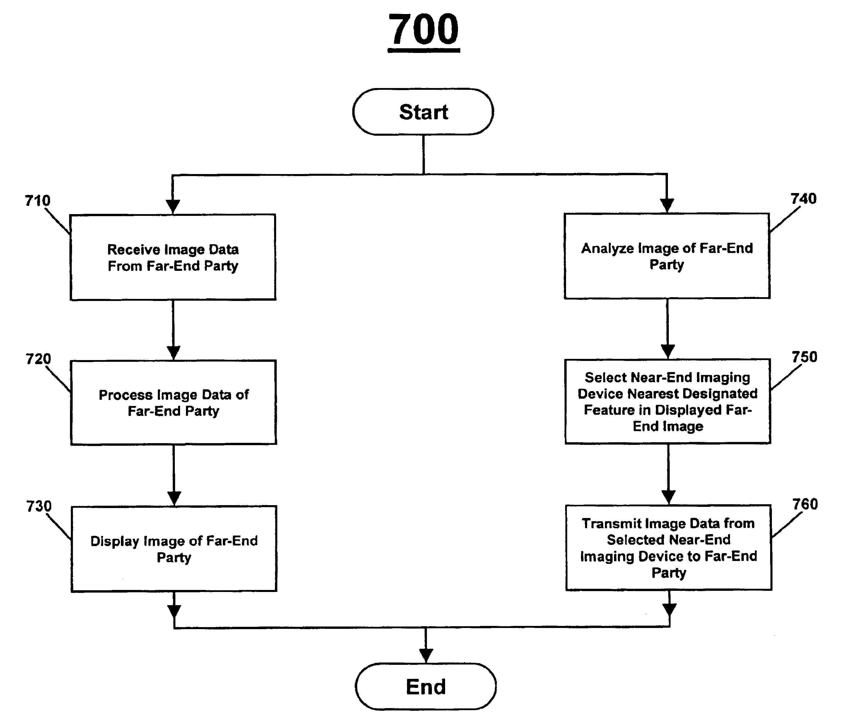
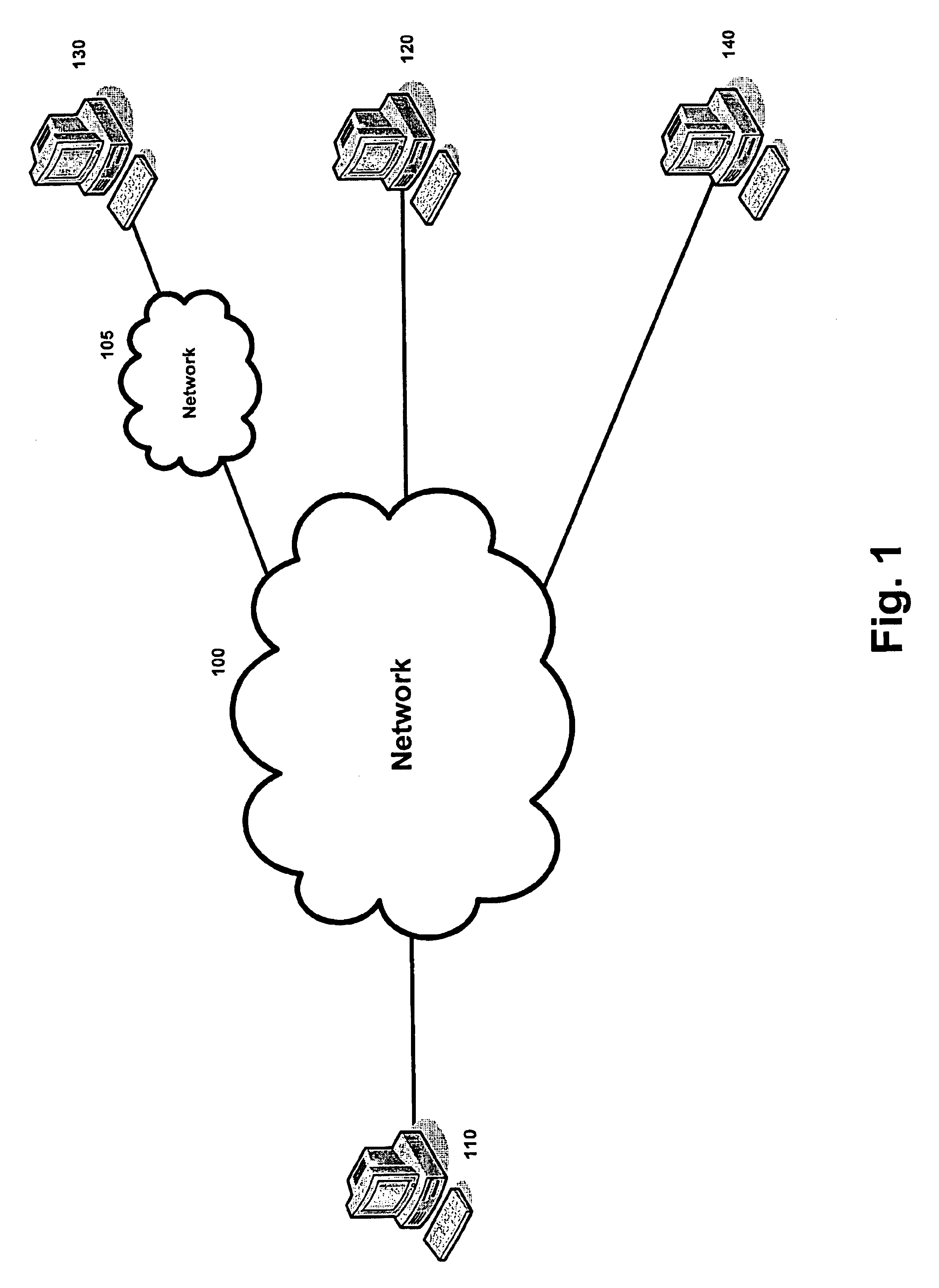
[0021]FIG. 1 is a block diagram of an exemplary communication network in which an embodiment of the present may be practiced. As illustrated in FIG. 1, communication network 100 may interconnect video telephony devices 110, 120, and 140, and is linked to video telephony device 130 through communication network 105. Each of video telephony devices 110, 120, 130, and 140 permit the two-way exchange of real-time images between two or more parties. Although the following detailed description will illustrate the operation of an embodiment of the present invention in terms of communication between two parties (referring to them as the “near-end” and “far-end” parties), restriction to two parties is for illustrative purposes only and is not a limitation of the present invention. Communication networks 100 and 105 may be, for example, wired packet networks based upon synchronous optical network (SONET), synchronous digital hierarchy (SDH), asynchronous transfer mode (ATM), 10 / 100 / 1000 megab...


PUM


Abstract

A two-way visual communication device and methods for operating such a device are disclosed. An embodiment of the disclosed invention may comprise a visual display device and one or more pinhole imaging devices positioned within the active display area of the visual display. An image processor may be used to analyze the displayed image, and to select the output signal from one of the pinhole imaging devices. The image processor may also modify the displayed image in order to optimize the degree of eye contact as perceived by the far-end party.

Description

CROSS-REFERENCE TO RELATED APPLICATIONS / INCORPORATION BY REFERENCE[0001][Not Applicable.]FEDERALLY SPONSORED RESEARCH OR DEVELOPMENT[0002][Not Applicable][MICROFICHE / COPYRIGHT REFERENCE][0003][Not Applicable]BACKGROUND OF THE INVENTION[0004]In general, interpersonal two-way visual communications devices have failed to meet the public acceptance that was expected of them following their introduction. One of the factors that may hinder usage growth is an unnatural component of the user interface of a typical two-way visual communication device. In normal face-to-face conversation, eye contact is considered to be both polite and desirable, and the avoidance of eye contact may be taken as an indication of evasiveness or deception. Because the imaging device in a typical two-way visual communication system is located outside of the viewing area of the local visual display, users making eye contact with the image of the far-end party are actually perceived by the far-end party as avoiding...

Claims


Application Information

Patent Timeline
Patent Type & Authority Patents(United States)
IPC IPC(8): H04N7/14
CPCH04N7/144
Inventor RAMBO, DARWINHOUGHTON, PHILIP
Owner AVAGO TECH INT SALES PTE LTD
Why Eureka
Try Eureka