Designating an image processing apparatus based on limited selection conditions

a technology of image processing and selection conditions, applied in the direction of digital output to print units, instruments, electrographic processes, etc., can solve the problems of cumbersome operation, unsuitable, system requires inefficient operation in a case, etc., and achieve the effect of reducing cumbersome operation by an operator

Inactive Publication Date: 2005-05-03
CANON KK
View PDF18 Cites 23 Cited by
  • Summary
  • Abstract
  • Description
  • Claims
  • Application Information

AI Technical Summary

Benefits of technology

[0007]The present invention has been made in consideration of the above situation, and has as its object to enable automatic selection of an image output apparatus suitable to the output form of an image, whereby reducing cumbersome operation by an operator.
[0015]It is preferable in the foregoing data processing apparatus that, in a case where the obtained output form designates to select an image output apparatus which completes execution of the image output job in a short time period, the selection means selects an image output apparatus which can perform output operation in the designated output form, based on the state of the image output job assigned to each of the image output apparatuses and the content of the image output job.

Problems solved by technology

Such operation is quite cumbersome and not desirable from the standpoint of efficient office work.
In addition, the above-described system requires inefficient operation in a case where an operator needs to select a printer based on its function, e.g., a printer capable of color printing, printer having high resolution, printer capable of both-sides printing and so forth.

Method used


Image

  • Designating an image processing apparatus based on limited selection conditions
  • Designating an image processing apparatus based on limited selection conditions
  • Designating an image processing apparatus based on limited selection conditions

Examples


operation example 1

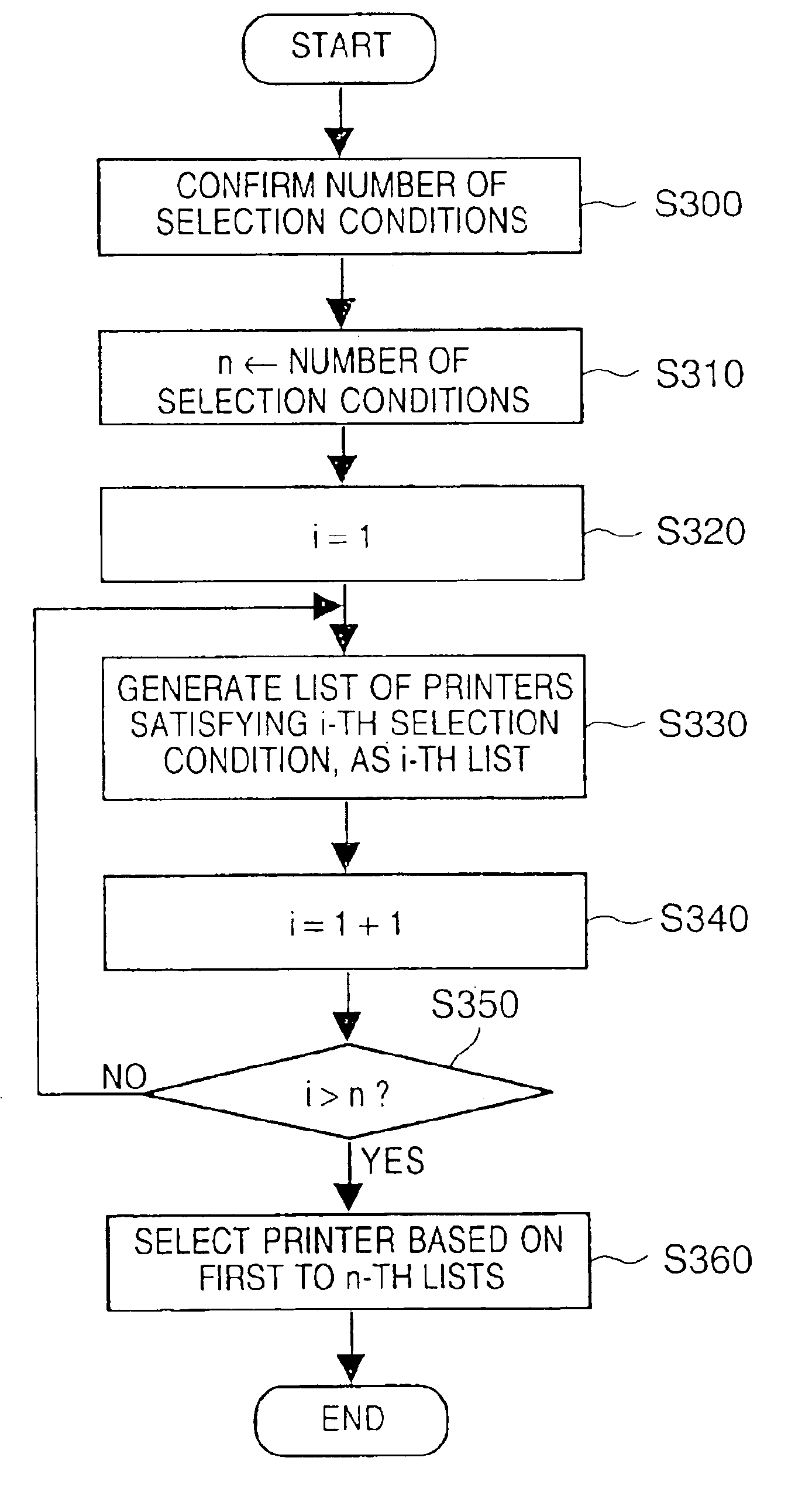
[0060]Operation Example 1 relates to the processing in step S140 (FIG. 3), performed in a case where the selection condition data obtained in step S120 designates to select a printer which completes execution of the print job in the shortest time period.

[0061]FIG. 4 is a flowchart showing a part of specific processing contents performed in step S140.

[0062]In step S200, it is determined whether or not the selection condition data, inputted by the operator in step S120, designates a printer which completes the print job execution in the shortest time period. If the result of determination is YES, the processing proceeds to step S210, while if the result is NO, the processing proceeds to step S250.

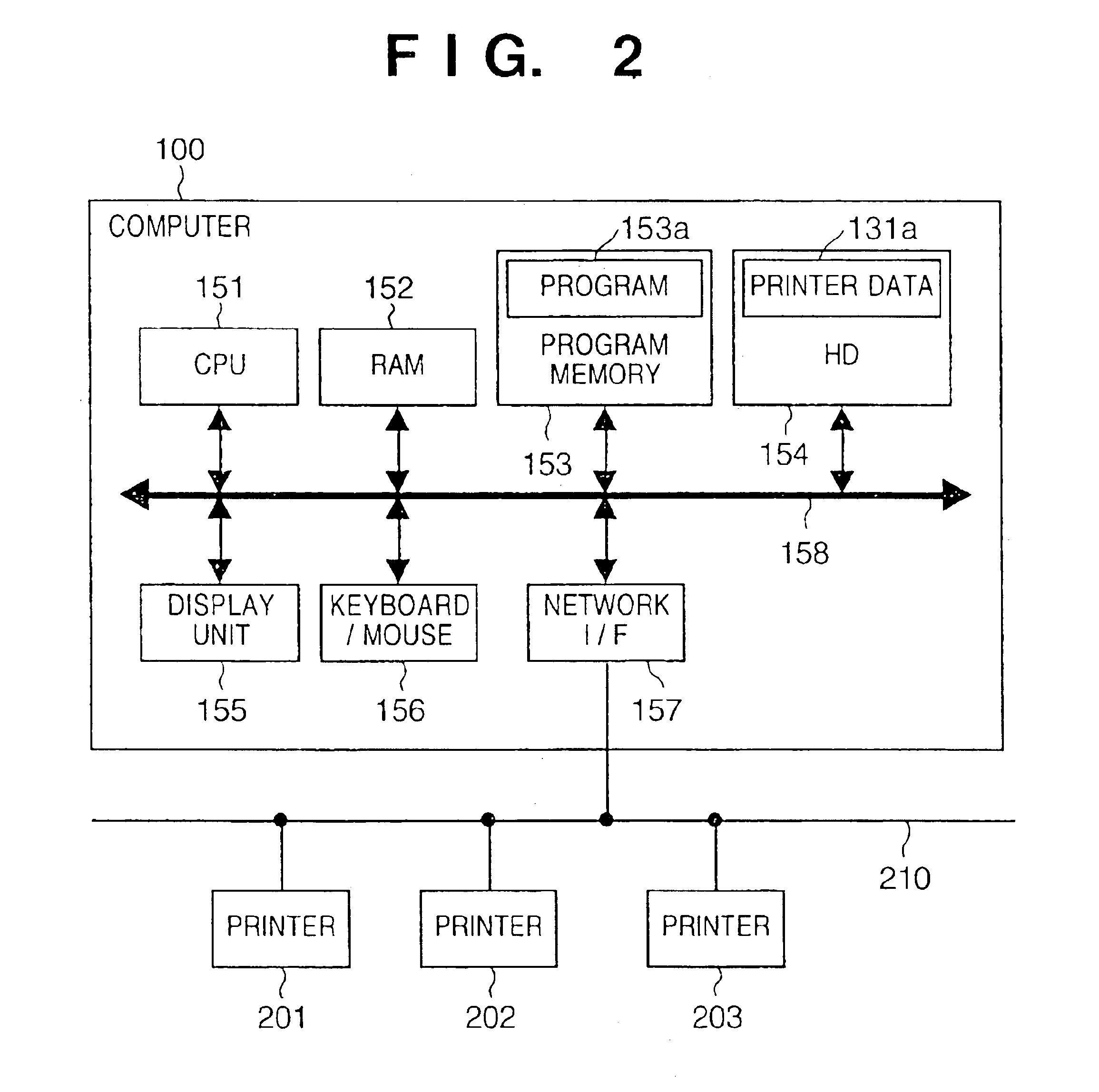
[0063]In step S210, job control data, indicative of progress of the print job assigned to each printer, is obtained. Note that the job control data is controlled by, for instance, another program (e.g., which constitutes a part of the program 153a) provided for controlling print jobs.

[0064]In...

operation example 2

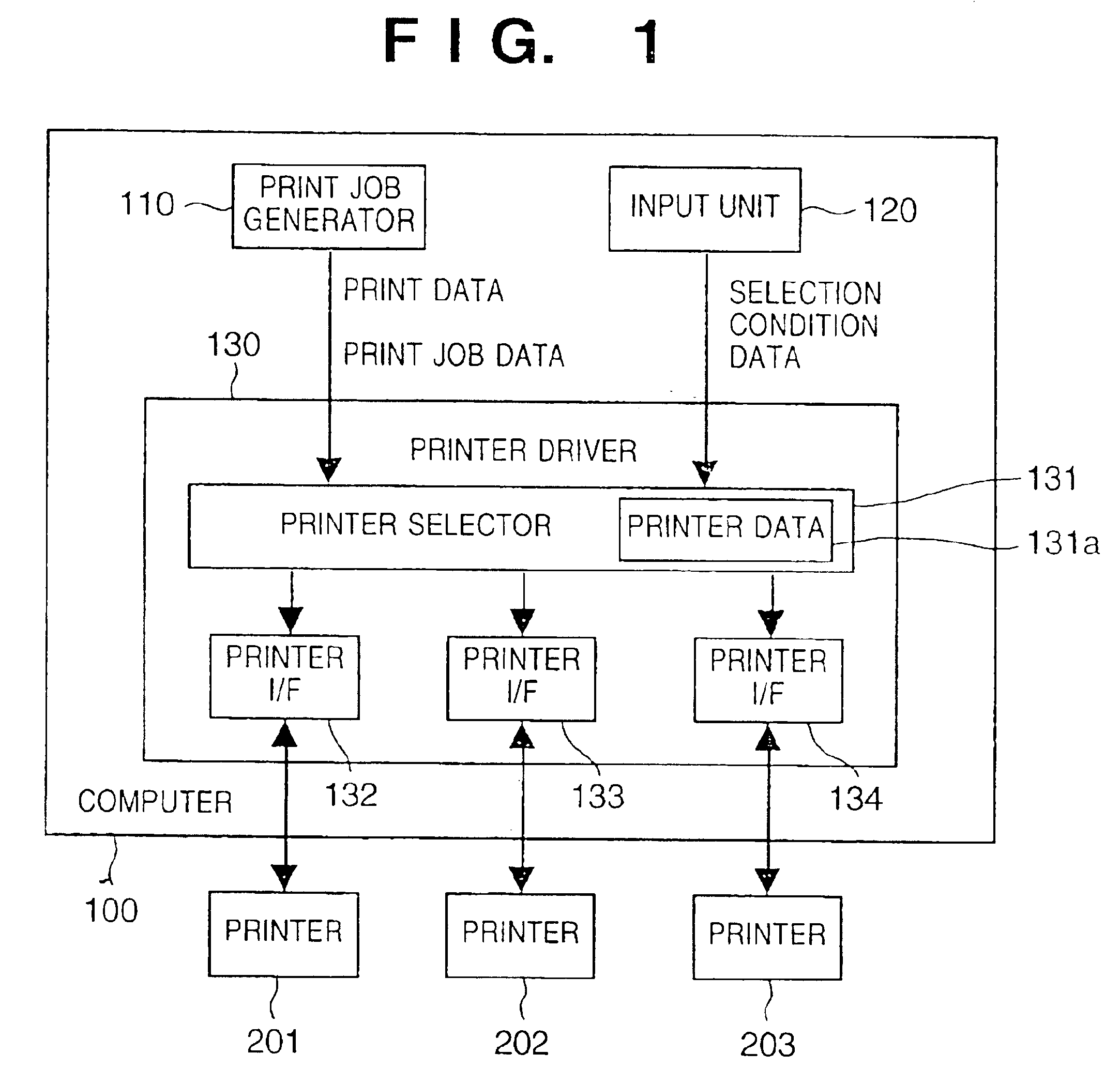
[0076]Operation Example 2 relates to print processing performed in a case where the selection condition data obtained in step S120 (FIG. 3) designates to select a printer capable of color printing.

[0077]According to the operation example 2, a printer capable of color printing is selected based on the printer data in step S140 in FIG. 3, then a message identifying the selected printer is displayed on the display unit 155 in step S150, and the print job is assigned to the selected printer in step S160.

[0078]The processing in step S140 in this case is explained by adapting the flowchart shown in FIG. 4. In step S200, determination is made that the selection condition data does not designate the “printer which completes the print job execution in the shortest time period.” Therefore, the processing proceeds to step S250 where a printer satisfying the designated selection condition (printer capable of color printing) is selected.

operation example 3

[0079]Operation Example 3 relates to print processing performed in a case where the selection condition data obtained in step S120 (FIG. 3) designates to select a printer capable of both-sides printing.

[0080]According to the operation example 3, a printer capable of both-sides printing is selected based on the printer data in step S140 in FIG. 3, then a message identifying the selected printer is displayed on the display unit 155 in step S150, and the print job is assigned to the selected printer in step S160.

[0081]The processing in step S140 in this case is explained by adapting the flowchart shown in FIG. 4. In step S200, determination is made that the selection condition data does not designate the “printer which completes the print job execution in the shortest time period.” Therefore, the processing proceeds to step S250 where a printer satisfying the designated selection condition (printer capable of both-sides printing) is selected.


PUM


Abstract

The present invention relates to a system having a computer and a plurality of printers connected to the computer. A printer selector selects a printer which can perform printing in the output form inputted by an operator through an input unit such as a keyboard or the like, based on print job data or printer data or the like. By inputting the output form, a printer having desired function e.g., printer capable of color printing or capable of both-sides printing and the like, is automatically selected.

Description

BACKGROUND OF THE INVENTION[0001]The present invention relates to a data processing apparatus and method thereof, a memory medium and a program. More particularly, the present invention relates to a data processing apparatus comprising connection means for connecting the data processing apparatus with a plurality of image output apparatuses, a data processing method for executing an image output job by selecting one of the plurality of image output apparatuses, and a memory medium as well as a program for controlling the data processing.[0002]Conventionally, to execute print processing in a system consisting of a computer and a plurality of printers, an operator has to select a printer which is suitable to contents of the print processing. FIG. 7 is a block diagram showing a schematic construction of the conventional printer system.[0003]A printer driver 330 included in a computer 300 receives print data related to a print job generated by a print job generator 310, and also receive...

Claims


Application Information

Patent Timeline
Patent Type & Authority Patents(United States)
IPC IPC(8): G06F3/12B41J29/38
CPCG06F3/1204G06F3/1285G06F3/126
Inventor KOANA, RYUZOU
Owner CANON KK
Why Eureka
Try Eureka