Lighting source device of adaptive regulating light-intensity in machine visual measuring system

A technology of machine vision measurement and self-adaptive adjustment, applied to measuring devices, lighting devices, light sources, etc., can solve the problem of low accuracy of image measurement

Inactive Publication Date: 2005-03-23
HARBIN INST OF TECH
View PDF0 Cites 19 Cited by
  • Summary
  • Abstract
  • Description
  • Claims
  • Application Information

AI Technical Summary

Problems solved by technology

[0003] In order to solve the defect that the existing technology can only rely on human subjective judgment to adjust the light intensity of the lighting source, resulting in low image measurement

Method used


Image

  • Lighting source device of adaptive regulating light-intensity in machine visual measuring system
  • Lighting source device of adaptive regulating light-intensity in machine visual measuring system
  • Lighting source device of adaptive regulating light-intensity in machine visual measuring system

Examples


specific Embodiment approach 1

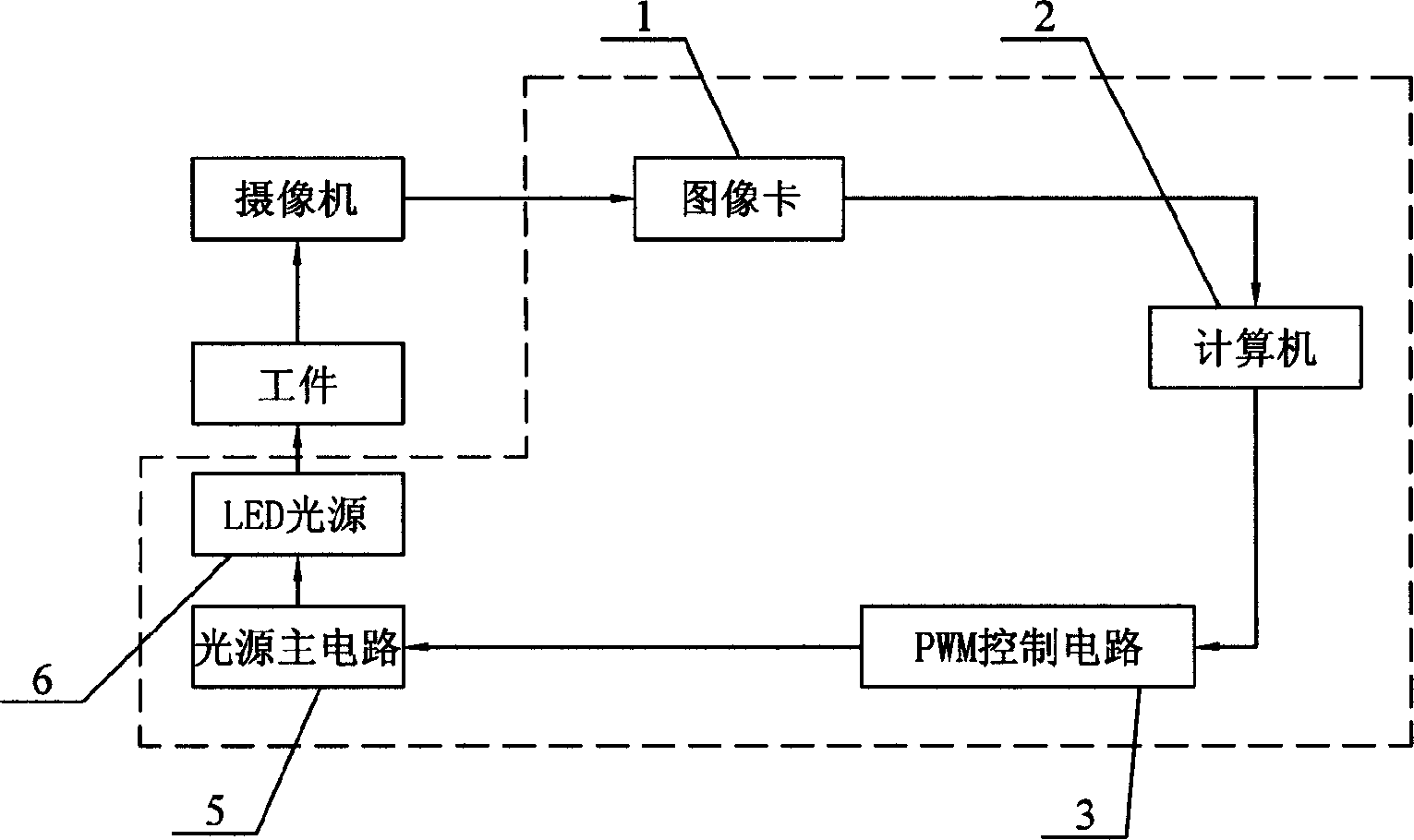
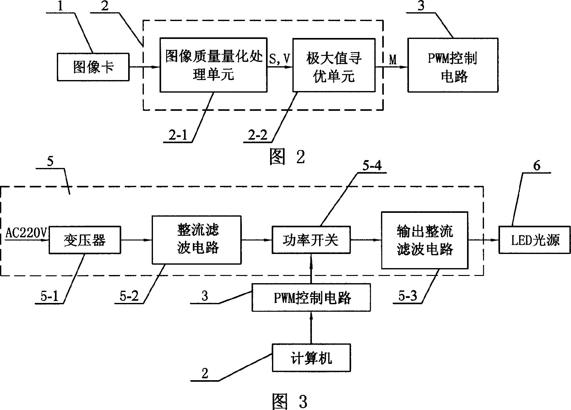
[0005] Specific implementation mode one: the following combination figure 1 This embodiment will be specifically described with FIG. 2 . It is composed of image card 1, computer 2, PWM control circuit 3, LED light source 6 and light source main circuit 5. The data output end of image card 1 is connected to the data input end of computer 2, and the output end of computer 2 is connected to the PWM control circuit 3. The input end and the output end of the PWM control circuit 3 are connected to the control end of the light source main circuit 5 , and the output end of the light source main circuit 5 is connected to the input end of the LED light source 6 . The arithmetic module in the computer 2 is composed of the image quality quantization processing unit 2-1 which calculates the image grayscale standard deviation function S and the image variance function V according to the signal input by the image card 1, and the image quality quantization processing unit 2-1 according to the...

specific Embodiment approach 2

[0011] Specific Embodiment 2: The present embodiment will be specifically described below with reference to FIG. 3 . The difference between this embodiment and Embodiment 1 is that the light source main circuit 5 is composed of a transformer 5-1, a rectification filter circuit 5-2, an output rectification filter circuit 5-3 and a power switch 5-4, and the input of the transformer 5-1 The terminal is connected to 220V AC mains, the output terminal of the transformer 5-1 is connected to the input terminal of the rectification filter circuit 5-2, the output terminal of the rectification filter circuit 5-2 is connected to one end of the power switch 5-4, and the other end of the power switch 5-4 One end is connected to the input end of the output rectification filter circuit 5-3, and the output end of the output rectification filter circuit 5-3 is connected to the input end of the LED light source 6. Other components and connections are the same as those in Embodiment 1.

specific Embodiment approach 3

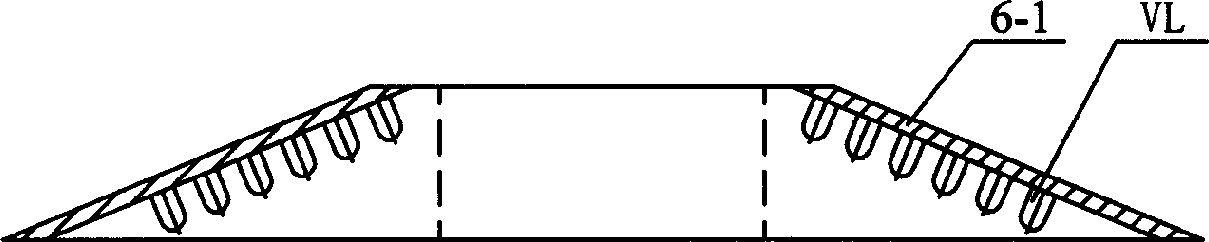
[0012] Specific implementation mode three: the following combination Figure 4 This embodiment will be specifically described. The difference between this embodiment and Embodiment 1 is that the LED light source 6 is a circular array of several light emitting diodes VL, and the light emitting diodes VL are arranged on the inner surface of the condensing cover 6-1. This setting can save power, and it is a cold light source.


PUM


Abstract

This invention discloses an illumination light source device for adaptively adjusting light intensity composed of an image card, a computer, PWM control circuit, LED light source and a light source main circuit, among which, the data output end of the image card is connected with the input end of the computer its output end is linked to the input end of PWM control circuit, its output end is connected with the control end of the light source main circuit, output of which is linked to the input of LED source, its operation module is formed by an image quality quantization process unit computing image gray standard difference and variance functions according to signals input by the card and maximum unit of the optimum supply current corresponding value.

Description

Technical field: [0001] The invention relates to an illumination light source device for self-adaptive adjustment of light intensity used in a machine vision precision measurement system. The light source actively adjusts the radiation intensity of the light source according to the illuminance of the surface of the workpiece to be measured, so that the workpiece to be measured is always in the measurement process. In top lighting condition. Background technique: [0002] For passive machine vision measurement systems, it mainly relies on ambient light or the light source attached to the conventional optical system for illumination. The quality of illumination has a great influence on the measurement accuracy of the system. Often, the accuracy of visual image measurement is reduced due to the low quality of illumination during measurement. Bring large errors to the measurement results. At present, the light source used in the machine vision measurement system is adjusted by ...

Claims


Application Information

Patent Timeline
IPC IPC(8): G01N21/84H05B37/02
Inventor 浦昭邦屈玉福刘国栋
Owner HARBIN INST OF TECH
Why Eureka
Try Eureka