High dynamic range laser far-field focal spot measurement device and method

A high dynamic range, far-field focal spot technology, applied in the optical field, can solve problems such as limited resolution, detector damage, focal spot distortion, etc., to achieve the effect of ensuring measurement accuracy, high confidence, and high stability

Inactive Publication Date: 2014-09-10
XI'AN INST OF OPTICS & FINE MECHANICS - CHINESE ACAD OF SCI
View PDF4 Cites 30 Cited by
  • Summary
  • Abstract
  • Description
  • Claims
  • Application Information

AI Technical Summary

Problems solved by technology

The disadvantages are: 1) Since the energy density ratio of the main lobe of the strong laser and the side lobe of the edge can reach several orders of magnitude, which is far beyond the dynamic range of the CCD, the laser focal spot image tested by this method is actually The main lobe distribution of the strong laser focal spot, while the information of the side lobe is covered; 2) The aberration of the focusing lens introduces focal spot distortion, which affects the test accuracy of the far-field focal spot
Its disadvantages are: 1) limited by the linear dynamic range of the recording medium, the array image cannot fully reflect the side lobe information of the laser far-field focal spot; 2) the array camera adopts an off-axis reflective mechanical structure, although the system adjustment has a It is convenient, but the aberration introduced is relatively large; 3) the resolution of the recording medium, namely CCD, is limited, and a certain relative error is introduced when calculating the focal spot diameter of the array image, thereby affecting the test accuracy of the system
The disadvantages are: 1) It is difficult to debug the system, the ratio of the two pairs of split beams is different, and it is difficult to reconstruct the focal spot; 2) Due to the excessive number of focal spots in one row or column, it is difficult to Completely record all information of the focal plane row or column
The disadvantages are: 1) The main lobe and side lobe of the laser far-field focal spot are time-sharing measurements, which are easily affected by the time-domain noise of the detector, ambient airflow disturbance and laser instability; 2) the method The random drift of the laser far-field focal spot is required to be small, which increases the requirements for the beam control system; 3) When measuring the side lobe, the main lobe needs to be blocked by this method, otherwise it will cause damage to the detector, so the performance requirements for the blocked device Relatively high, it must be tightly shielded from light, resistant to laser radiation, and not affect the measurement results

Method used


Image

  • High dynamic range laser far-field focal spot measurement device and method
  • High dynamic range laser far-field focal spot measurement device and method
  • High dynamic range laser far-field focal spot measurement device and method

Examples


Embodiment Construction

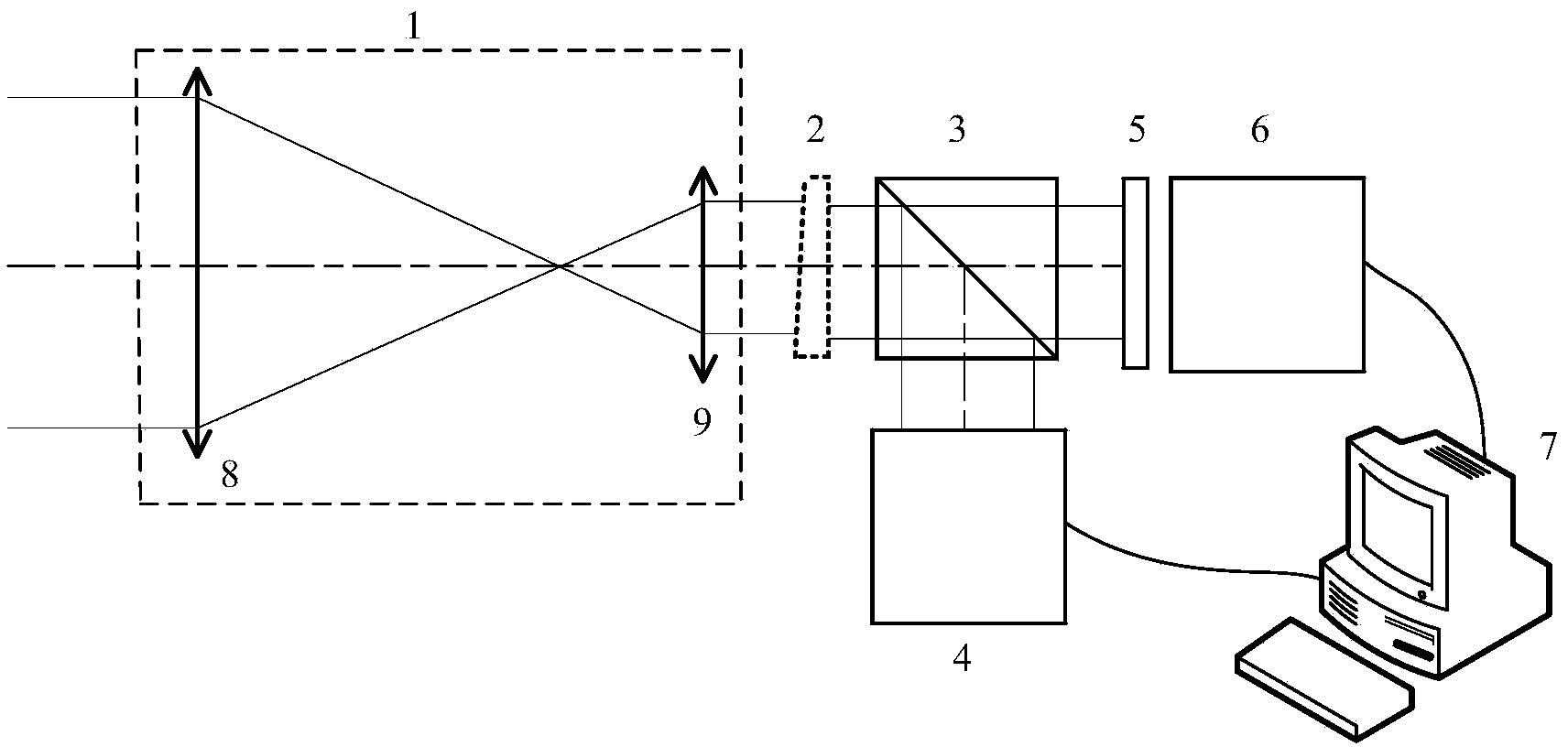
[0028] Such as figure 1 As shown, the present invention consists of a laser beam shrinkage / expansion system 1, an attenuation wedge 2, a beam splitter 3, a scientific grade CCD detector 4, a microlens array 5, a CCD detector 6, and a control computer 7. The laser beam reduction / expansion system 1 is composed of an objective lens 8 and an eyepiece 9, which is a Keplerian structure, adopts a double-telecentric optical path, and performs an achromatic design to ensure the wide-spectrum operation of the test system and eliminate the position error of the detector. influence on the measurement results. Select the laser beam shrinking / expanding system 1 that matches the beam shrinking / expanding ratio according to the measured laser beam aperture. According to the energy of the laser beam to be measured, the attenuation wedge 2 with a suitable attenuation ratio is selected to ensure that the scientific grade CCD detector 4 and the CCD detector 6 work in the linear response region. ...


PUM


Abstract

The invention relates to a high dynamic range laser far-field focal spot measurement device and method. The high dynamic range laser far-field focal spot measurement device comprises a laser beam shrinkage or expander system, an attenuation wedge plate, a spectroscope, a scientific grade CCD (Charge Coupled Device) detector, a micro lens array, a CCD detector and a control computer; the laser beam shrinkage or expander system, the attenuation wedge plate and the spectroscope are arranged on the same light path in turn; the light incident to the spectroscope is divided into the transmission light and the reflected light through the spectroscope; the scientific grade CCD detector is arranged on a light path of the reflected light after the reflected light passes through the spectroscope; the micro lens array and the CCD detector are arranged on a light path of the refracted light in turn after the refracted light passes through the spectroscope; the scientific grade CCD detector and the CCD detector are connected with the control computer. According to the high dynamic range laser far-field focal spot measurement device and method, the dynamic measurement on high dynamic range laser far-field focal spots can be achieved and the measurement accuracy can be well ensured.

Description

technical field [0001] The invention belongs to the field of optics, and relates to a high dynamic range laser far-field focal spot measurement device and method, in particular to a laser far-field focal spot reconstruction based on Fourier optics theory to realize a high dynamic range laser far-field focal spot Measuring device and its method. Background technique [0002] The laser far-field focal spot is an important index to describe the quality of the output beam of a large laser device, and it is also the main parameter to characterize the ability of the laser beam to enter the hole in the inertial confinement fusion system. Due to the great disparity in the optical energy density aberration between the main lobe and the side lobe of the laser far-field focal spot (above 10000:1), there is no detector with such a high dynamic range. At present, the laser far-field focal spot measurement methods mainly include: long focal length lens imaging method, array camera test m...

Claims


Application Information

Patent Timeline
Patent Type & Authority Applications(China)
IPC IPC(8): G01J1/42G01B11/00G01M11/02
Inventor 段亚轩陈永权龙江波赵建科田留德李坤薛勋
Owner XI'AN INST OF OPTICS & FINE MECHANICS - CHINESE ACAD OF SCI
Why Eureka
Try Eureka