
Fan blade

a fan blade and fan blade technology, applied in the direction of machines/engines, mechanical equipment, liquid fuel engines, etc., can solve the problems of wood as a blade material having other problems, natural appearance, and plastic and metal being often too heavy

Inactive Publication Date: 2005-05-10
CARTWRIGHT THOMAS
View PDF61 Cites 36 Cited by
  • Summary
  • Abstract
  • Description
  • Claims
  • Application Information

AI Technical Summary

Benefits of technology

[0008]In accordance with other aspects of the invention, the elongated member has one or more channels that have a floor and sidewalls spaced apart by the floor. ...

Problems solved by technology

However, these are often woven together and are free to rotate about a central axis because the natural fibers are no strong enough to withstand normal rotational and aerodynamic forces.
Plastic and metal are often too heavy and otherwise do not present a natural appearance.
Wood as a blade material has other problems.
Dense woods such as oak or mahogany are often too heavy for conventional light-weight fan motors, although it is possible to increase the bearing size of the fan motor.
Due to thermal cycling and operational stress, the laminated wooden blades may crack along the length of the blade.
Under impact the blade could separate into one or more pieces and send harmful missiles about a room.

Method used


Image

  • Fan blade
  • Fan blade
  • Fan blade

Examples


embodiment 16

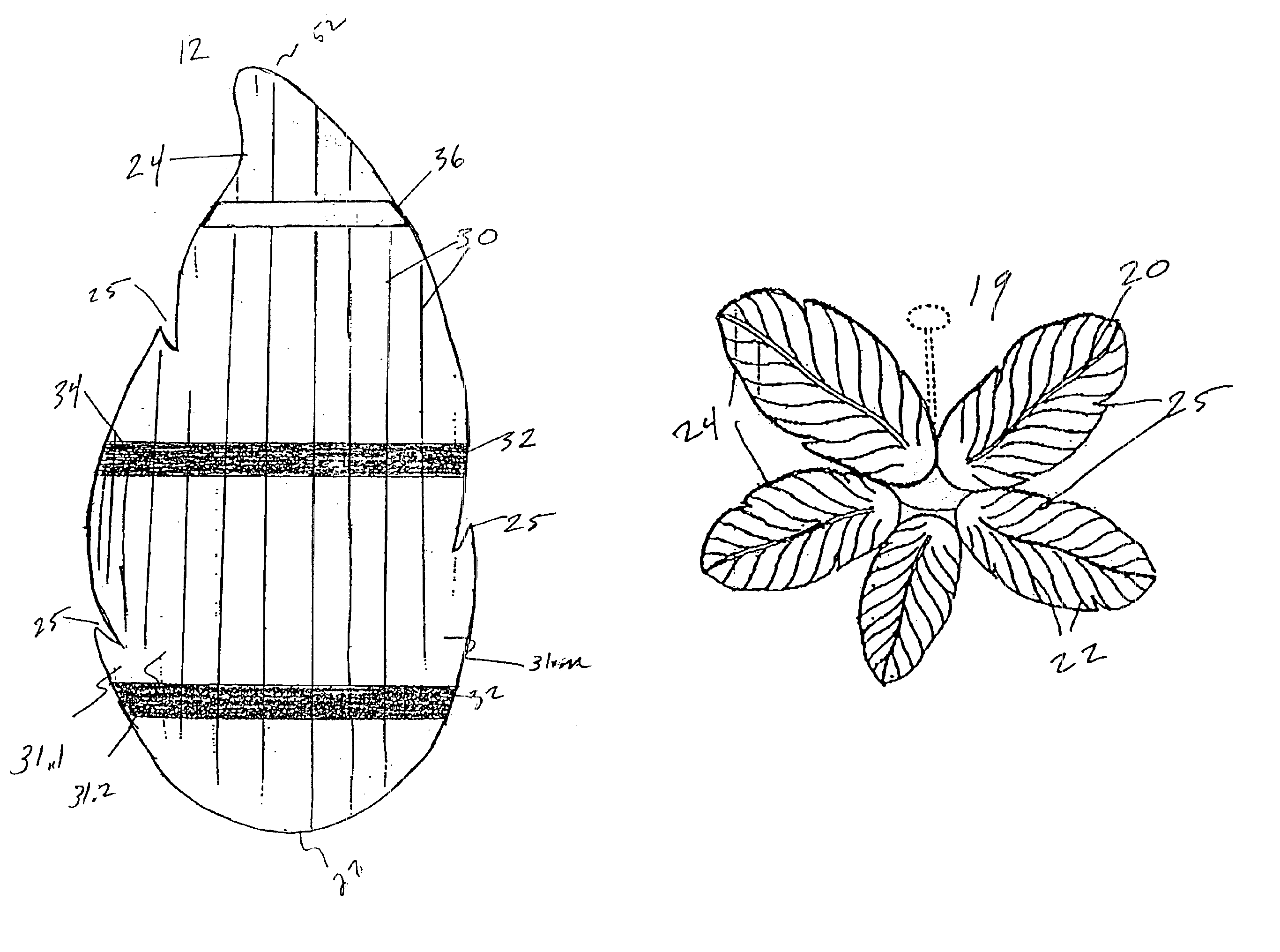
[0031]FIGS. 7, 8&9 are alternate surface patterns and shapes that might also be achieved by this process. Each will feature cross braces 32 arranged in the same manner as described above. In one alternate embodiment 16 the central vein 20 is straighter than is some other embodiments and the contoured sections 26 are more uniform. The lateral or peripheral veins 22 extend in an equally more uniform fashion. The undulating perimeter 24 remains, but the indentations 25 are removed.

embodiment 17

[0032]In a second alternate embodiment 17 the central vein 20 and the peripheral veins are less uniform and, again, serpentine. The contouring 26 is accordingly less uniform as is the undulation 24. One novel difference is the rounding of the indentations 25 around the perimeter.

embodiment 18

[0033]In a third alternate embodiment 18 the central vein is straight 20. The lateral veins 22 and contouring 26 are uniform, decreasing in size as the contouring 26 moves farther from the base 27. The perimeter does not undulate.

[0034]FIG. 10 is a rendering of the possible arrangement of the described blade as used in a ceiling fan.

[0035]It will be appreciated by those of ordinary skill in the art having the benefit of this disclosure that the embodiment of the transverse opposing grain bracing is capable of numerous variations without departing from the scope and spirit of the invention. It is fully intended that the invention for which a patent is sought encompasses within its scope all such variations without being limited to the specific embodiment disclosed above. For example, there are equivalent means for bracing the sheet or strips of wood. These include and are not limited to applying a fabric, such as a mesh, and glue to the reverse side to keep the strips together. The c...


PUM

PropertyMeasurementUnit
Lengthaaaaaaaaaa
Widthaaaaaaaaaa

Abstract

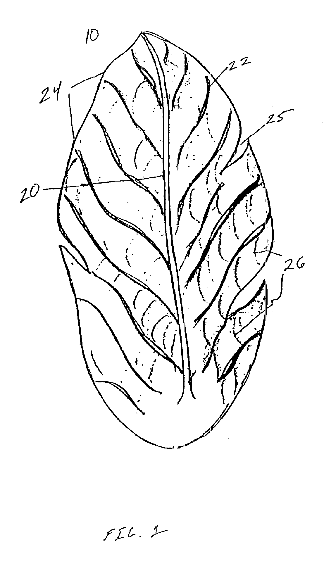
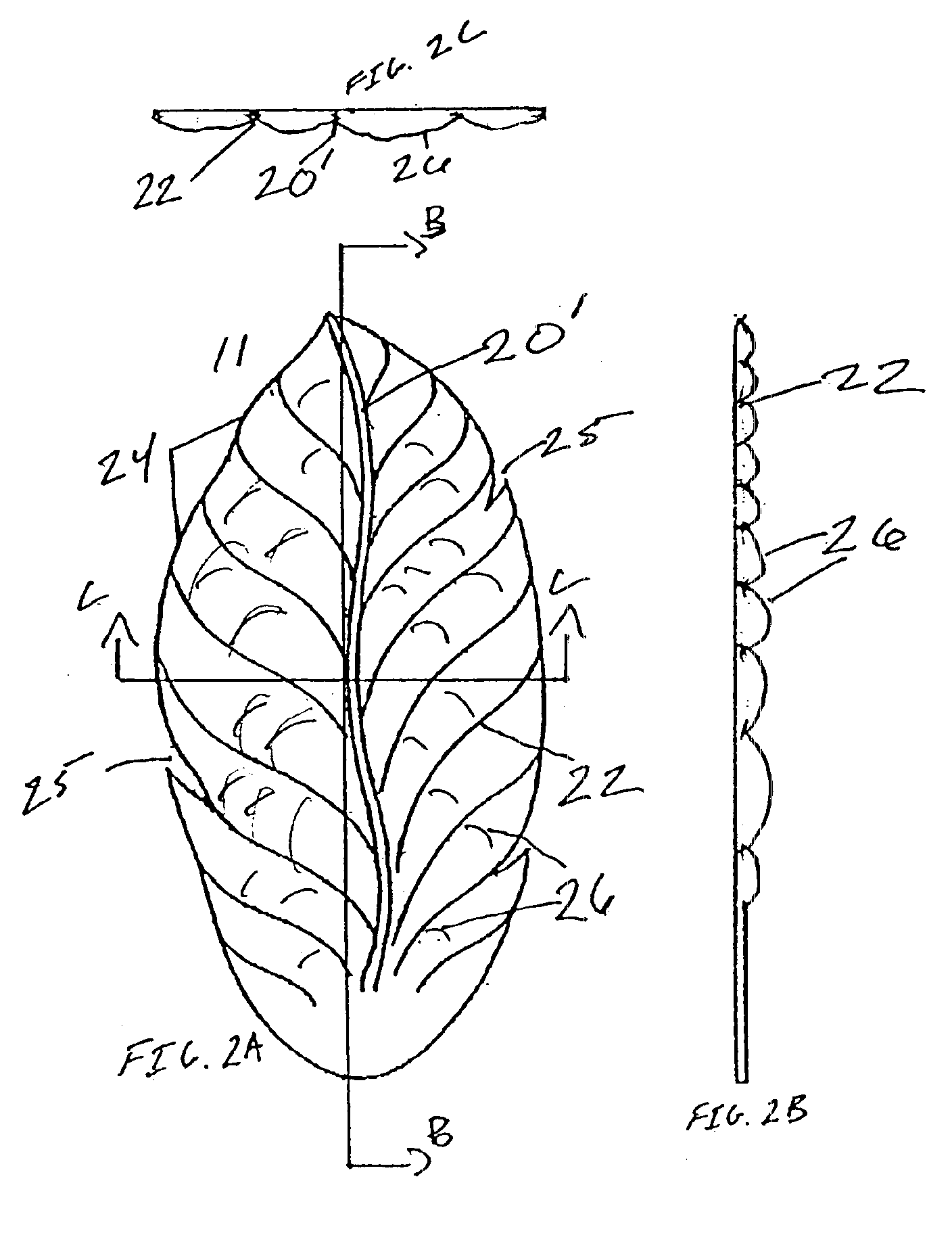
A fan blade has a three dimensional shape that resembles a leaf. The blade is made of balsa or other suitable wood with the grain of the wood running along its length. The obverse surface of the blade is contoured and has a central vein and lateral veins running from the central vein to opposite edges. The reverse side has one or more channels. Braces are set in the channels. The braces are also made of balsa or comparable wood and their grain runs transverse to the direction of the gain of the blade.

Description

CROSS-REFERENCE TO RELATED APPLICATIONS[0001]This application is a continuation-in-part of and claims the benefit of the priority date of U.S. Des. application Ser. No. 29 / 162,811 filed Jun. 21, 2002 (abandoned) and U.S. Des. application Ser. No. 29 / 159,732 filed Apr. 29, 2002 now issued as U.S. Des. Pat. No. D491,657.BACKGROUND[0002]The field of this invention relates in general to ceiling fans, and in particular to light weight, wooden fan blades that resemble items or nature such as leaves.[0003]Ceiling fans a popular commercial and consumer items. They move air in a room to more evenly distribute the air and thus keep the room at a more constant temperature. Ceiling fans are often used to cool people by providing a stream of air over their bodies. The air stream enhances body cooling by evaporating any surface body moisture and by removing heat from the surface of the skin.[0004]Ceiling fans also have a decorative function. Their blades can assume a variety of shapes and can be ...

Claims


Application Information

Patent Timeline
IPC IPC(8): F04D29/02F04D29/00F04D29/38
CPCF04D29/384F04D29/023F05D2300/42
Inventor CARTWRIGHT, THOMAS
Owner CARTWRIGHT THOMAS
Learn More