Meltblowing apparatus

a technology of melt blowing apparatus and die assembly, which is applied in the direction of melting spinning methods, applications, manufacturing tools, etc., can solve the problems of high undesirable fluid flow from the fluid orifice after the fluid supply is terminated, the fabrication requirements are at the limit, and the cost prohibitive of die fabrication requirements

Inactive Publication Date: 2005-05-10
ILLINOIS TOOL WORKS INC
View PDF134 Cites 68 Cited by
  • Summary
  • Abstract
  • Description
  • Claims
  • Application Information

AI Technical Summary

Benefits of technology

[0010]It is also an object of the invention to provide novel meltblowing methods and apparatuses that are economical ...

Problems solved by technology

In applications that require accurate dispensing of a meltblown fluid including the application of meltblown adhesives onto substrates, however, any continued fluid flow from the fluid orifice after the fluid supply...

Method used


Image

  • Meltblowing apparatus
  • Meltblowing apparatus
  • Meltblowing apparatus

Examples


Embodiment Construction

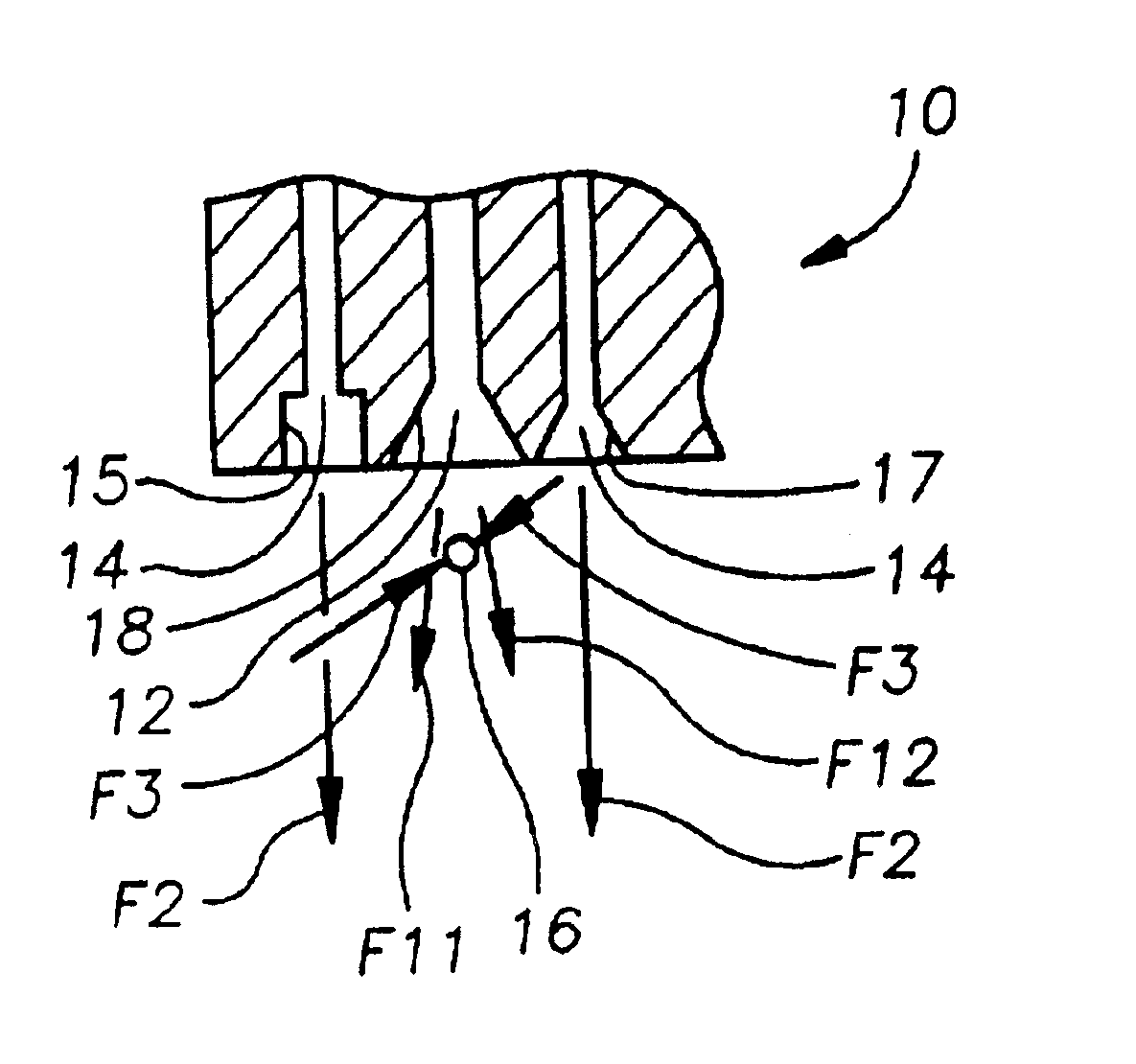
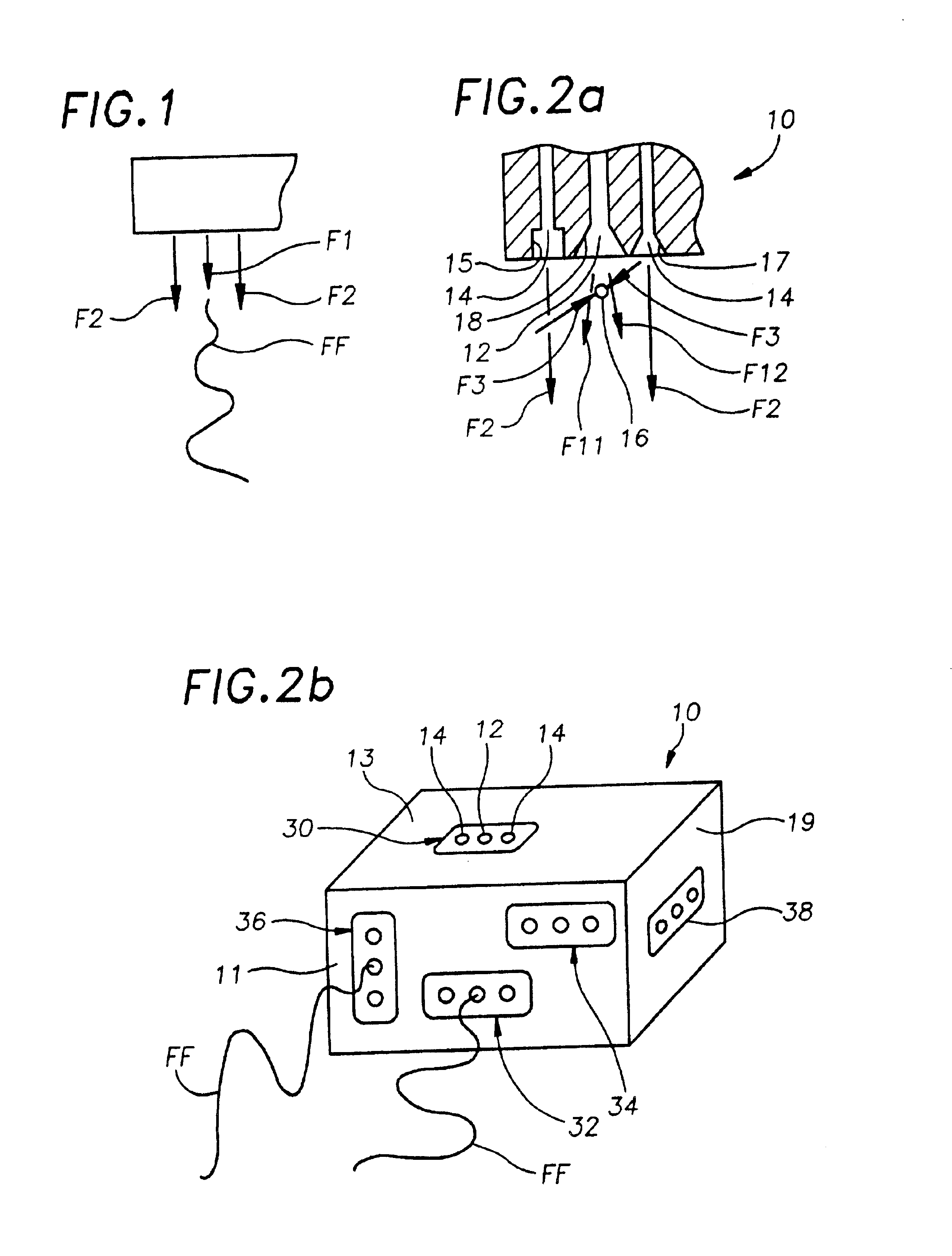
[0026]FIG. 1 is a diagrammatic view of a meltblowing process or method wherein a first fluid is dispensed to form a fluid flow F1 at a first velocity and a second fluid is dispensed to form separate second fluid flows F2 at a second velocity along substantially opposing flanking sides of the first fluid flow F1. According to this configuration, the first fluid flow F1 is located between the separate second fluid flows F2, wherein the substantially opposing sides of the first fluid flow F1 are each flanked by the second fluid flows F2 to form an array of fluid flows as shown in FIG. 1. The second velocity of the second fluid flows F2 is greater than the first velocity of the first fluid flow F1 so that the second fluid flows F2 draw and attenuate the first fluid flow F1 to form a first fluid filament FF. The length of the arrows F1 and F2 is indicative of, though not proportional to, the relative velocities therebetween. The first fluid flow F1 and the second fluid flows F2 are direc...


PUM

PropertyMeasurementUnit
Velocityaaaaaaaaaa

Abstract

A meltblowing apparatus for dispensing an adhesive through a plurality of first orifices of a die assembly fabricated from a plurality of laminated members to form a plurality of adhesive flows at a first velocity and dispensing air through a plurality of second orifices in the die assembly to form a plurality of air flows at a second velocity. The plurality of first and second orifices arranged in an alternating series so that each of the plurality of first orifices is flanked on substantially opposing sides by one of the plurality of second orifices, wherein the plurality of first and second orifices are oriented to direct non-convergently the plurality of adhesive flows and the plurality of air flows.

Description

CROSS REFERENCE TO RELATED APPLICATIONS[0001]The present application is a continuation of U.S. application Ser. No. 09 / 255,906 filed on 20 Feb. 1999, now U.S. Pat. No. 6,074,597, which is a continuation of U.S. application Ser. No. 08 / 717,080 filed on 10 Oct. 1996, now U.S. Pat. No. 5,902,540, issued on 11 May 1999, both of which are fully incorporated herein by reference.BACKGROUND OF THE INVENTION[0002]The invention relates generally to meltblowing processes and to die assemblies for practicing meltblowing processes, and more particularly to die assemblies with a plurality of adhesive dispensing orifices flanked on each side by air dispensing orifices, wherein adhesive flows from the plurality of adhesive dispensing orifices are drawn and attenuated by relatively high velocity, high temperature air flows from the air dispensing orifices to form adhesive filaments.[0003]Meltblowing is a process of forming fibers or filaments by drawing and attenuating a first fluid flow, like molte...

Claims


Application Information

Patent Timeline
IPC IPC(8): D01D5/08D01D5/098B05B7/08B05C5/02B29C48/30D01D4/02D01D4/08D04H1/56D04H1/72D04H3/16
CPCB05C5/0279D04H1/565D01D5/0985D01D4/025B05B7/0884D04H1/56B29C49/00
Inventor KWOK, KUI-CHIUVAN ERDEN, DONALDZENTMYER, HUGH
Owner ILLINOIS TOOL WORKS INC
Why Eureka
Try Eureka