
Remotely controllable automatic door operator and closer

a remote control, automatic door technology, applied in the direction of mechanical actuation of burglar alarms, instruments, wing accessories, etc., can solve the problems of inability to benefit from door opening devices, inconvenient manual operation of doors for users, and general prohibition of “do-it-yourself installation

Inactive Publication Date: 2005-05-10
ECCLESTON JON E
View PDF3 Cites 111 Cited by
  • Summary
  • Abstract
  • Description
  • Claims
  • Application Information

AI Technical Summary

Benefits of technology

[0013]In summary, one aspect of the present invention is directed to a door operator apparatus mountable to a doorframe structure and a movable door to control door movement between a closed position and an opened position. The operator apparatus preferably is remotely controllable and typically includes a motor assembly, a linkage device, a slip clutch assembly, and a controller unit. The motor assembly preferably has an output shaft, with the motor mountable to one of the door and the doorframe structure. The linkage device is preferably mountable to the other of the door and th

Problems solved by technology

Door opening devices are frequently found in commercial establishments such as airports, malls or supermarkets where manual operation of the door may be inconvenient to users.
Unfortunately, however, many factors make it unfeasible for such individuals to benefit from door opening devices.
Many door operators are pneumatically, hydraulically, or electro-mechanically driven, and typically require substantial operating current and / or voltage.
As a result, “do-it-yourself” installation is generally precluded.
The resultant cost of permits, equipment, and labor often prevents handicapped individuals from purchasing door operators for use at home and at work.
In addition, conventional door operators often are expensive to maintain.
Additionally, the installation may vary with each model, adding to the installation complexity.
Most door operators are large, bulky units that employ high torque, low rpm electric motors that require at least a minimal amount of gear reduction.
Unfortunately, this combination is required because the device must be capable of being back-driven manually when not powered.
Motors of this type are typically large when compared to high rpm motors of equivalent horsepower.
Due to the large size of the magnets necessary to generate such a high torque at a low rpm, the motor and associated gear reduction mechanisms are relatively large.
Often, these bulky door operators are too large to mount directly to the door and must be mounted on or above the door lintel.
This may decrease the overall aesthetic appeal and, without substantial structural modification, may preclude installation and operation of the unit altogether.
For example, in a retrofit installation where the upper portion or edge of the door is at or very near the ceiling, the amount of space provided between the door lintel and the ceiling may be insufficient to mount the unit.
This has an unfortunate result of substantially increasing the force required to manually move the door when the operator is not powered.
A power outrage can render a door thus equipped into a frozen state potentially trapping people in hazardous situations.
However, this spring force must not be so large as to prevent or substantially impair manual operation of the door, especially for physically impaired individuals.
These opposing limitations often result in poor closing performance in windy conditions.
This configuration is difficult to install and adjust due in part to the utilized mechanical cams and overall size of the door opener.
Moreover, with a power failure, an individual attempting to open or close the door may have to exert a substantial amount of manual force to overcome the resistance forces generated by the gear train, motor and / or internal or external door check spring.
As a result, such individuals may be trapped within a room whose exit includes an operator-equipped door that is frozen or inoperable to those individuals.
Unfortunately, this passive mode is a problem when this door operator is used on doors without a door latch, as is common with store front doors and public bathroom doors.
In addition the general public is accustomed to encountering resistance when opening a public door manually.

Method used


Image

  • Remotely controllable automatic door operator and closer
  • Remotely controllable automatic door operator and closer
  • Remotely controllable automatic door operator and closer

Examples


Embodiment Construction

[0021]Reference will now be made in detail to the preferred embodiments of the invention, examples of which are illustrated in the accompanying drawings. While the invention will be described in conjunction with the preferred embodiments, it will be understood that they are not intended to limit the invention to those embodiments. On the contrary, the invention is intended to cover alternatives, modifications and equivalents, which may be included within the spirit and scope of the invention as defined by the appended claims.

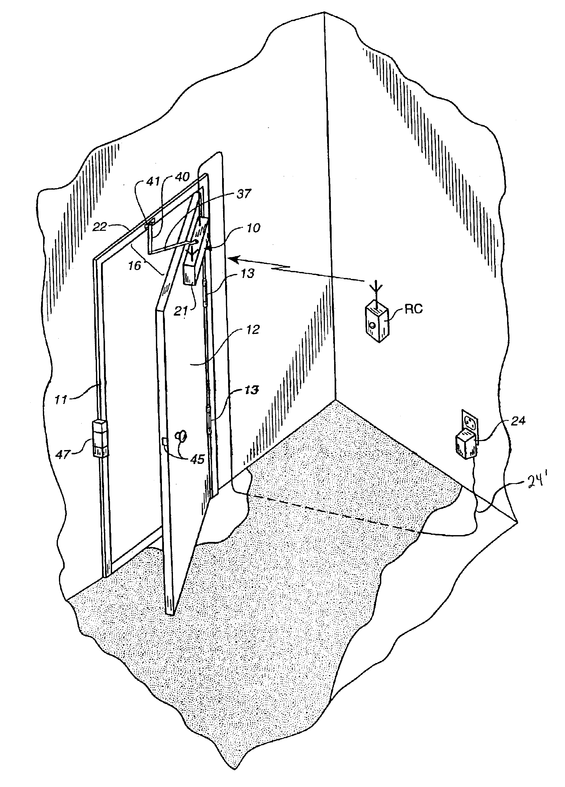
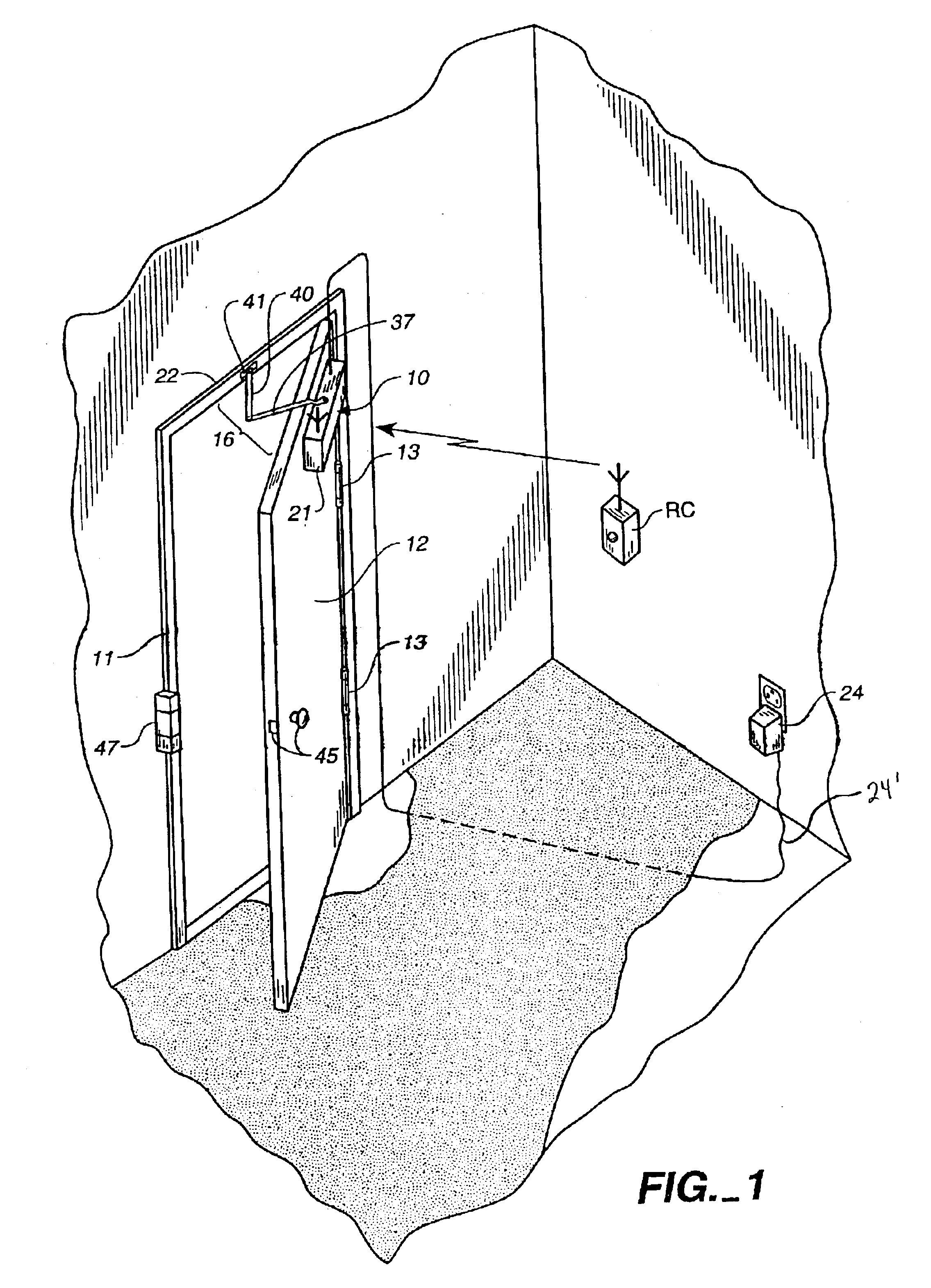
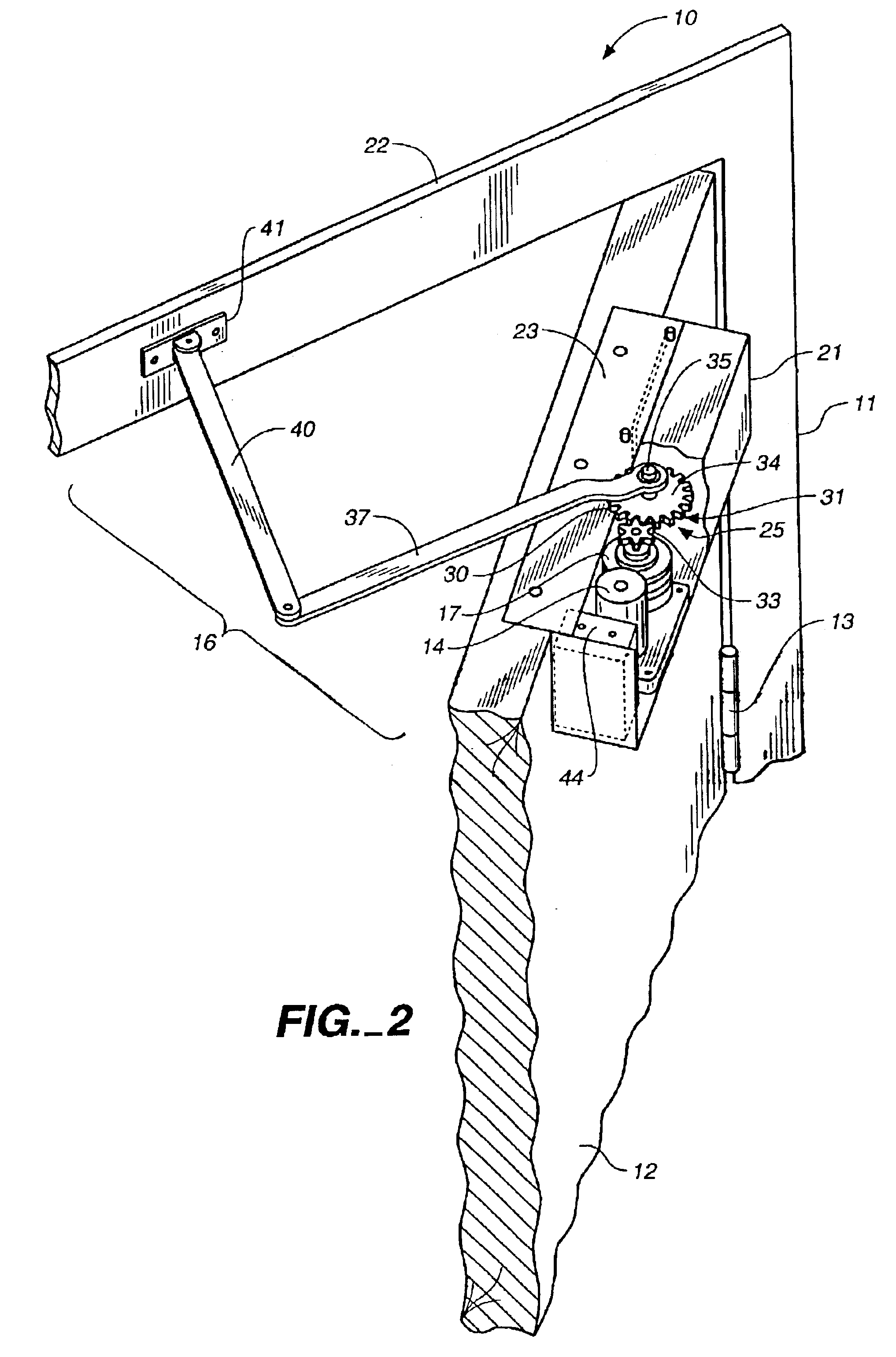
[0022]Turning now to the drawings, wherein like components are designated by like reference numerals throughout the various figures, attention is directed to FIGS. 1-4 where a door operator apparatus, generally designated 10, is illustrated in a mounted position between a doorframe structure 11 and a door 12. The door 12 is movably coupled to the doorframe structure 11 with a door-coupling device 13, to support movement of the door between a closed position (FIG...


PUM


Abstract

A remotely controllable door operator apparatus is mountable to a doorframe structure and a movable door to control door movement between a closed position and an opened position. The operator apparatus includes a motor assembly, a linkage device, a slip clutch assembly, and a controller unit. The motor assembly has an output shaft, and the motor is mountable to one of the door and the door frame structure. The slip clutch assembly is coupled between the output shaft and the linkage device to transfer torque therebetween, and can slip to enable manual and remote operation of the door. The controller unit is coupled to the motor assembly to activate the operator apparatus to close the door in manual operation, and to open and to close the door in response to at least one remote signal. A method of using the remotely controllable automatic door operator and closer is also disclosed.

Description

BACKGROUND OF THE INVENTION[0001]1. Field of the Invention[0002]This invention relates, in general, to automatic door operators and more particularly to automatic door operators that may be operated manually and remotely.[0003]2. Description of Related Art[0004]Door opening devices are frequently found in commercial establishments such as airports, malls or supermarkets where manual operation of the door may be inconvenient to users. Understandably, handicapped individuals, including bedridden and wheel chair confined individuals, would greatly benefit from door opening devices in their homes and businesses. Unfortunately, however, many factors make it unfeasible for such individuals to benefit from door opening devices.[0005]Many door operators are pneumatically, hydraulically, or electro-mechanically driven, and typically require substantial operating current and / or voltage. Installation of such an operator can include substantial modification to the door, the doorframe, and indee...

Claims


Application Information

Patent Timeline
IPC IPC(8): E05F15/12
CPCE05F15/63E05Y2201/236E05Y2400/612E05Y2900/132E05Y2800/11E05Y2400/3013
Inventor ECCLESTON, JON E.
Owner ECCLESTON JON E
Learn More