
Apparatus and method for packet scheduling

a packet scheduling and apparatus technology, applied in electrical apparatus, digital transmission, data switching networks, etc., can solve the problems of packet quality of service (qos) experienced by packets on a network, requiring excessive buffer space, and other applications cannot tolerate packet loss, so as to achieve fast scheduling

Inactive Publication Date: 2005-05-10
FUTUREWEI TECH INC
View PDF7 Cites 71 Cited by
  • Summary
  • Abstract
  • Description
  • Claims
  • Application Information

AI Technical Summary

Benefits of technology

[0025]Pipelining the tournament provides even faster scheduling. The tournament can be divided into two or more pipeline stages. Each level of the tree resides completely within one pipeline stage. When a match in the last level of stage i is completed, its re

Problems solved by technology

The quality of service (QoS) experienced by packets on a network is characterized by delay, jitter, and loss.
Streaming applications, such as video, can tolerate a large fixed delay but require excessive buffer space if the jitter or variation in delay experienced by different packets exceeds a threshold.
Other applications cannot tolerate packet loss, for example packets being dropped due to excessive congestion.
That is, the network makes an effort to deliver all packets in a reasonable amount of time but makes no guarantees about delay or loss.
Due to the bursty nature of network traffic, some packets may be delayed or dropped due to congestion, and the delay experienced by packets may vary considerably from packet to packet.
While best efforts delivery is adequate for many types of traffic, such as file-transfers and web page access, it is not suitable for other types of traffic, such as real-time audio and video streams.
For best efforts traffic, however, the packets in the queues have not been allocated a guaranteed bit rate on the output port.
Because of the processing overhead required for transmitting each packet with class-based queuing or per-flow queuing, these mechanisms are usually restricted to use on low-speed links and with a moderate number of queues (10s not 100s).

Method used


Image

  • Apparatus and method for packet scheduling
  • Apparatus and method for packet scheduling
  • Apparatus and method for packet scheduling

Examples


Embodiment Construction

[0049]A description of preferred embodiments of the invention follows.

Packet Scheduling Using Tournament Sort

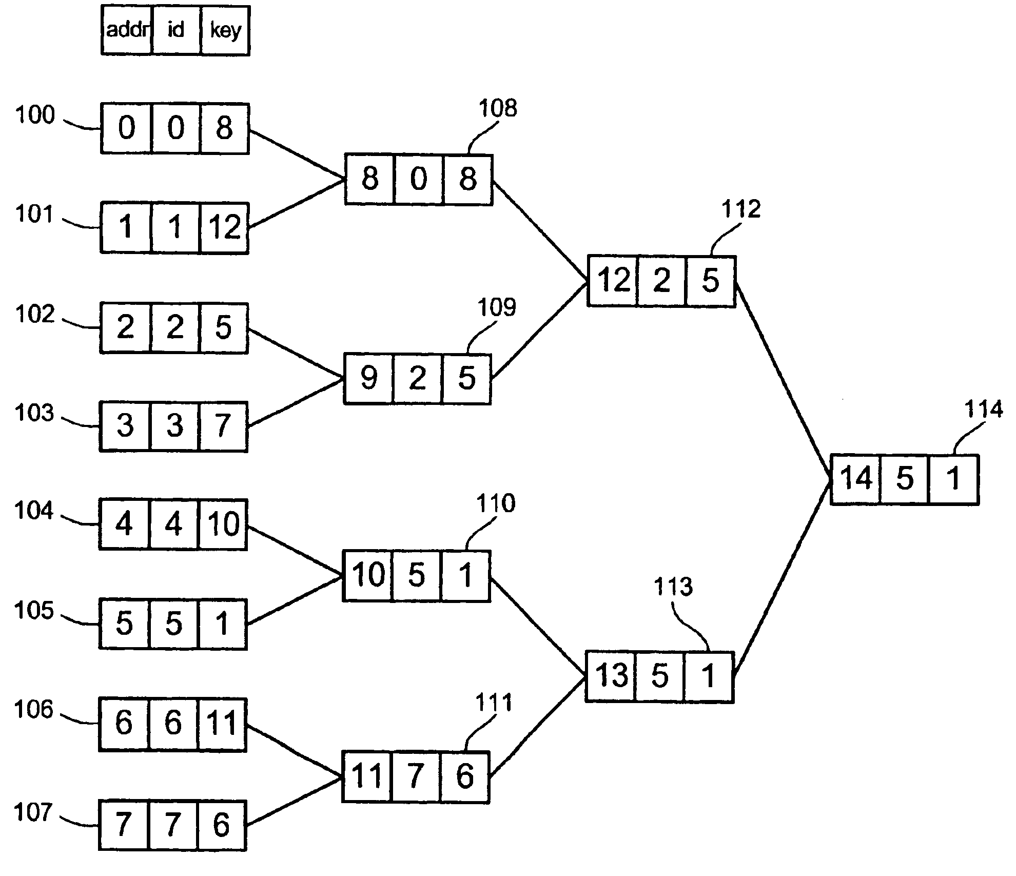
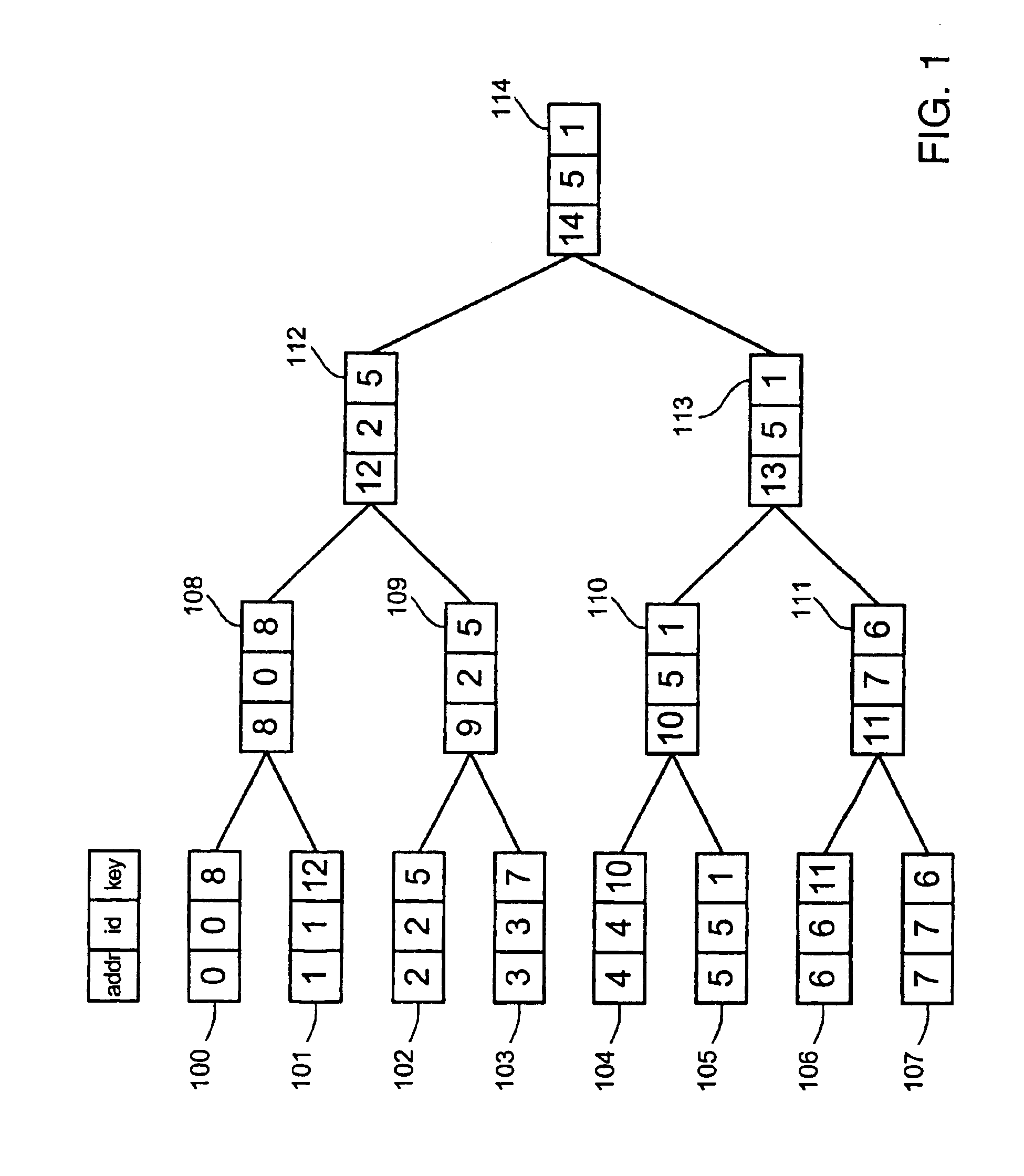
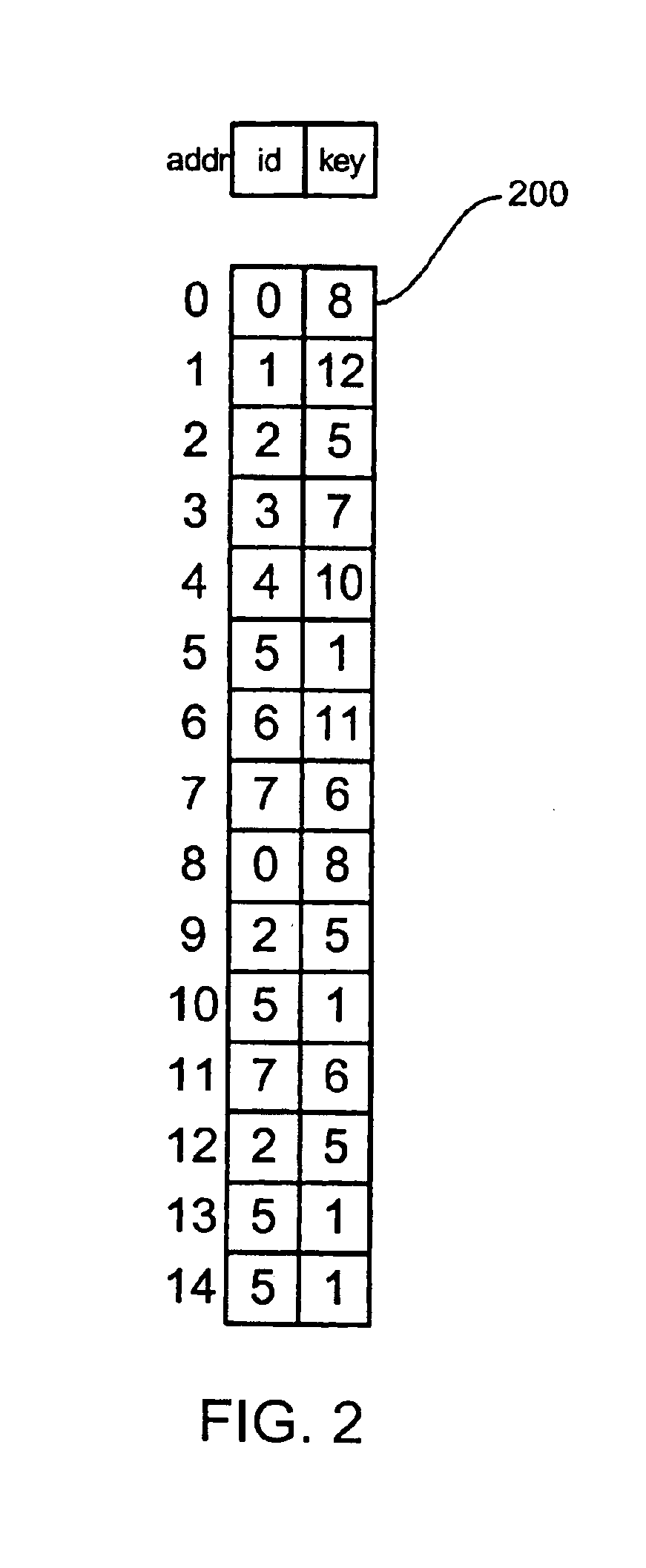
[0050]The data structure used to select the queue with the lowest counter is illustrated in FIG. 1. The figure shows a tree of triples. Each triple contains an address, a queue ID, and the associated counter value or key. The leaves of the tree 100-107 represent the counters associated with each queue. For each of these leaves, the address and queue ID are identical and the key holds the value of the counter associated with the identified queue. For clarity the figure shows only eight queues; however, in the preferred embodiment, there are 4,096 queues.

[0051]Each internal node of the tree 108-114 of FIG. 1 represents the results of a match in the tournament among the leaf nodes. For example, node 109 represents the result of a match between leaf nodes 102 and 103. Because node 102 has a lower key, it wins this match, and node 109 records this win by copying both the queue ID ...


PUM


Abstract

In a network router, a tree structure or a sorting network is used to compare scheduling values and select a packet to be forwarded from an appropriate queue. In the tree structure, each leaf represents the scheduling value of a queue and internal nodes of the structure represent winners in comparisons of scheduling values of sibling nodes of the tree structure. CBR scheduling values may first be compared to select a queue and, if transmission from a CBR queue is not timely, a packet may be selected using WFQ scheduling values. The scheduling values are updated to reflect variable packet lengths and byte stuffing in the prior packet. Scheduling may be performed in multiple stages.

Description

RELATED APPLICATION(S)[0001]This application claims the benefit of U.S. Provisional Application No. 60 / 153,148 filed Sep. 9, 1999, the entire teachings of which are incorporated herein by reference.BACKGROUND OF THE INVENTION[0002]The quality of service (QoS) experienced by packets on a network is characterized by delay, jitter, and loss. Many network applications are sensitive to one or more of these parameters. An interactive application, for example, becomes unusable if the total delay of the network exceeds a threshold. Streaming applications, such as video, can tolerate a large fixed delay but require excessive buffer space if the jitter or variation in delay experienced by different packets exceeds a threshold. Other applications cannot tolerate packet loss, for example packets being dropped due to excessive congestion.[0003]Most Internet traffic today is handled as a single class of traffic that is delivered on a best-effort basis. That is, the network makes an effort to deli...

Claims


Application Information

Patent Timeline
IPC IPC(8): H04L12/56
CPCH04L12/5693H04L47/10H04L47/2416H04L47/58H04L47/31H04L47/522H04L47/2441H04L47/50H04L12/28
Inventor DALLY, WILLIAM J.CARVEY, PHILIP P.BELIVEAU, PAUL A.MANN, WILLIAM F.DENNISON, LARRY R.
Owner FUTUREWEI TECH INC
Learn More