Self-spotting apparatus for free-weights

a self-spotting and free-weight technology, applied in the field of exercise equipment, can solve the problems of not being able to provide independent support of both ends of the barbell, needing one or more spotters, and not being able to prevent injury with quick response, etc., and achieve the effect of low cost, simple structure and ruggedness

Inactive Publication Date: 2005-05-17
CROSSROADS DEBT
View PDF6 Cites 46 Cited by
  • Summary
  • Abstract
  • Description
  • Claims
  • Application Information

AI Technical Summary

Benefits of technology

[0013]Therefore an object of the present invention is to provide a self-sp

Problems solved by technology

One disadvantage limiting use of free-weights is the need for one or more spotters, especially in strength regimens that push the strength and endurance limits of the user.
This is a safety concern if spotters are not immediately available since the user may be unable to safely lift the weight to a support device.
Even when spotters are available, they may not recognize an unsafe condition, or, their response may not be quick enough to prevent injury.
None of the afo

Method used


Image

  • Self-spotting apparatus for free-weights
  • Self-spotting apparatus for free-weights
  • Self-spotting apparatus for free-weights

Examples


embodiment 101

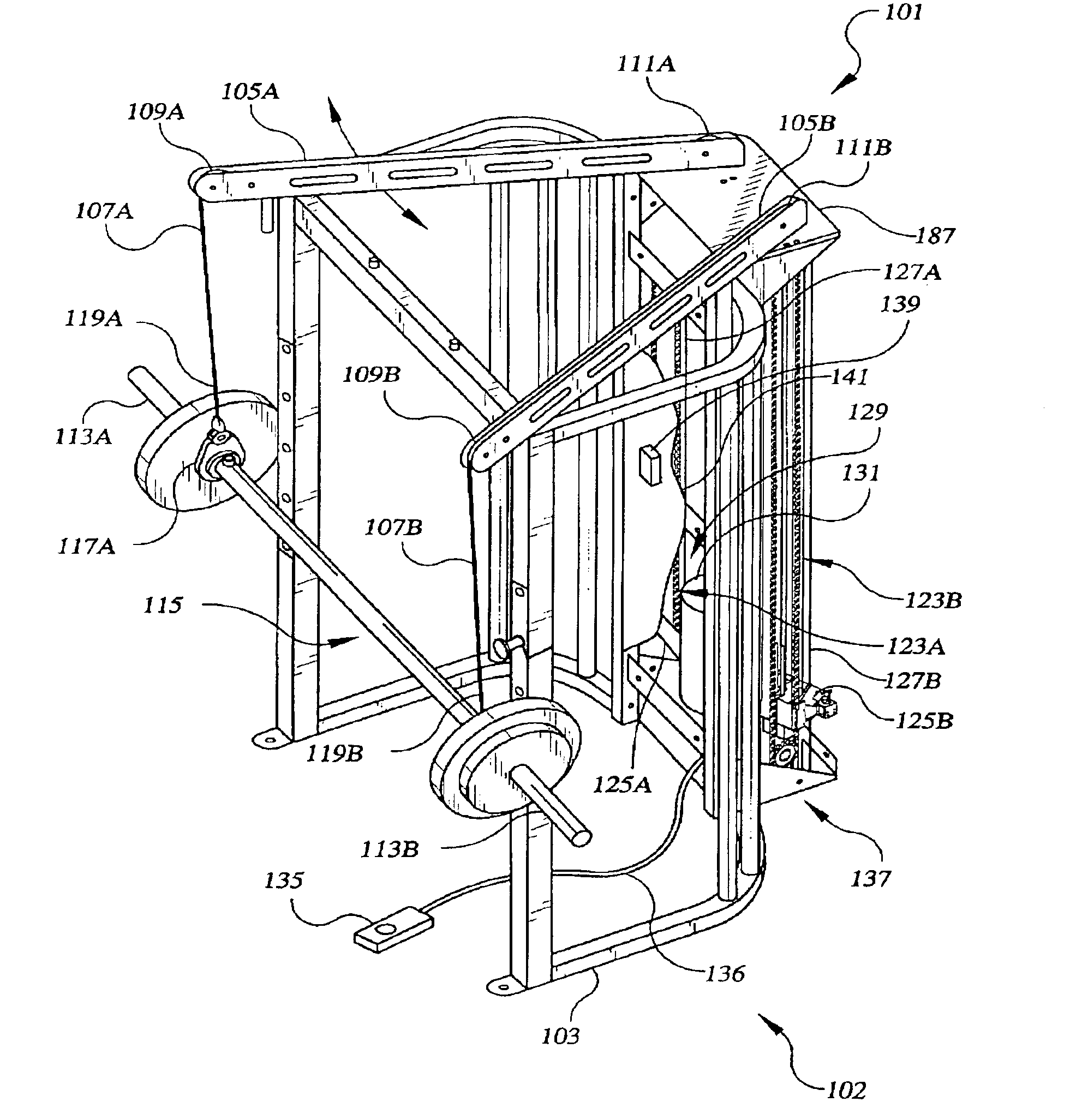
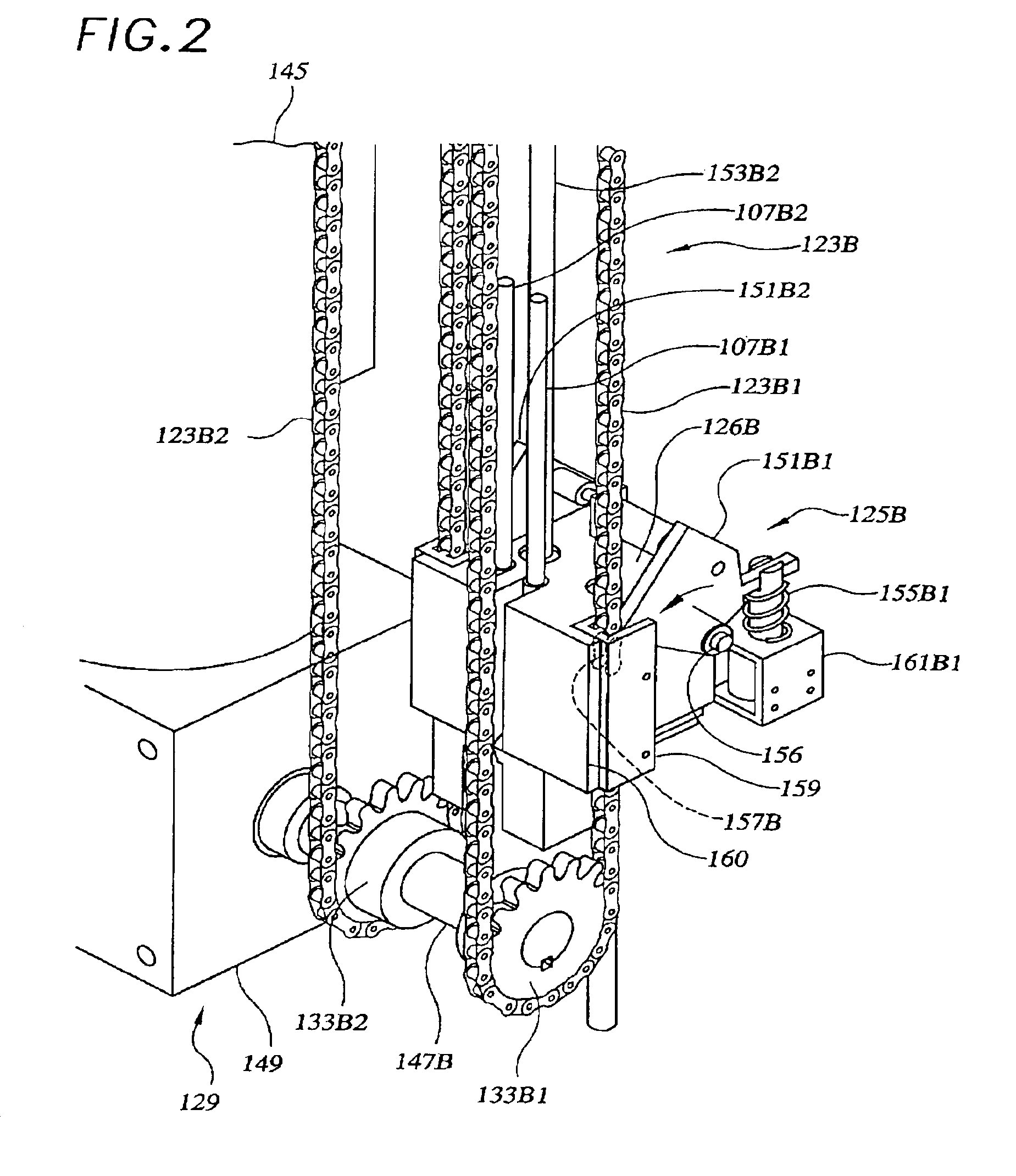
[0068]FIG. 1 is right front-quarter isometric drawing of embodiment 101 of the barbell spotting apparatus comprising a support stand 102 having a frame 103, tower enclosure 137 and pivoting weight-support booms 105A and 105B. Cable assemblies 107A and 107B, supported by sheaves 109A and 111A of boom 105A and sheaves 109B and 111B of boom 105B are attached to barbell ends 113A and 113B of a free-weight assembly such as barbell 115. Releasable attachments such as cable attachment assemblies 117A and 117B (shown most clearly in FIG. 7) connect respective cable assembly end portions 119A and 119B to barbell ends 113A and 113B.

[0069]Opposite cable assembly end portions 121A and 121B (121B shown best in FIG. 6) are connected to respective weight-support assemblies such as chain assemblies 123A and 123B through chain engagement blocks 125A and 125B. Engagement blocks 125A and 125B reciprocate vertically, constrained laterally by linear guides 127A and 127B and engage the respective chain a...

embodiment 1201

[0111]FIG. 12 is a perspective drawing of embodiment 1201 of a weight responsive engagement assembly 1203 and weight support assembly 1205 of the present invention. Weight support assembly 1205 consists of a load-bearing column 1207 supported vertically from a frame of the apparatus such as the frame 103 of FIG. 1. Cable assembly 1209 connects engagement assembly 1203 to a free weight assembly (not shown) via cable attachment assembly 1211. Sheaves 1213A and 1213B support cables 1215A, 1215B, similar to the sheaves of FIG. 1.

[0112]Engagement assembly 1203, better shown in detail perspective drawing FIG. 12A, utilizes a pawl of pawl assembly 1215 which engages one of a plurality of vertically-spaced holes 1217 in column 1207 of support assembly 1205. Pin 1219 retains attachment assembly 1221 of cable assembly 1209 to weight engagement assembly 1203. Clip 1223 retains pin 1219 in engagement with engagement assembly 1203 and attachment assembly 1221.

[0113]Weight responsive engagement a...


PUM


Abstract

A weight support assembly [1205] and weight-responsive engagement assembly [1203] for a self-spotting free weight apparatus utilizes engagement of a pawl assembly [1215] in one of a plurality of vertically-spaced holes [1217] of a column 1207 to support a cable assembly [1209]. The cable assembly attaches the bar of a free-weight assembly to the weight responsive engagement assembly by means of a cable attachment assembly [1211] and sheaves 1213A, 1213B.

Description

[0001]This application is a continuation-in-part application of U.S. application Ser. No. 09 / 957,152, filed Sep. 20, 2001, now U.S. Pat. No. 6,537,182, which is a divisional application of U.S. application Ser. No. 09 / 385,241, filed Aug. 28, 1999, issued as U.S. Pat. No. 6,293,892.BACKGROUND OF THE INVENTION[0002]1. Field of the Invention[0003]The present invention relates to the field of exercise equipment and, more particularly, to a self-spotting apparatus for free-weights.[0004]2. Description of the Related Art[0005]Despite the variety of exercise and muscle-building equipment and activities available, free-weight lifting continues to be the workout method of choice for many athletes. Free-weight lifting allows unrestrained motion during lifting, closely approximating application of human strength in many recreation and sporting activities. Selection of weights utilized in free-weight lifting is highly repeatable as compared to machines employing levers, cams, and resistance ele...

Claims


Application Information

Patent Timeline
IPC IPC(8): G05F1/10G05F1/45
CPCA63B21/078G05F1/45A63B2021/0786A63B21/0783
Inventor SLAWINSKI, MICHAEL D.
Owner CROSSROADS DEBT
Why Eureka
Try Eureka