
Dual motion arm powered treadmill

a treadmill and dual-motion technology, applied in the field of treadmills and motorless treadmills, can solve the problems of motors that make treadmills undesirable, motors that need maintenance, and need power sources

Inactive Publication Date: 2005-05-17
TRUE FITNESS TECH
View PDF31 Cites 65 Cited by
  • Summary
  • Abstract
  • Description
  • Claims
  • Application Information

AI Technical Summary

Benefits of technology

[0011]It is another further object to provide a manual treadmill wherein the power provided by the upper body of a user allows the incline of the treadmill exercise surface to be at a much shallower, more natural walking angle of the user.

Problems solved by technology

While conventional motor-driven treadmills provide a desirable exercise apparatus in appropriate settings, in other settings the motor makes such an apparatus undesirable.
For example, motors used in treadmills need maintenance, can fail, require a power source and add to the overall weight of the treadmill.
Finally, motor-driven treadmills are more expensive to purchase relative to motorless treadmills.
However, such a steep incline of the treadmill surface feels unnatural to the user, and is not at all like the user's normal walking motion.
However, due to the interlinked relationship of the arm members, both arm members must move at the same rate and in the opposite directions of one another, which may not be the preference of the user.

Method used


Image

  • Dual motion arm powered treadmill
  • Dual motion arm powered treadmill
  • Dual motion arm powered treadmill

Examples


Embodiment Construction

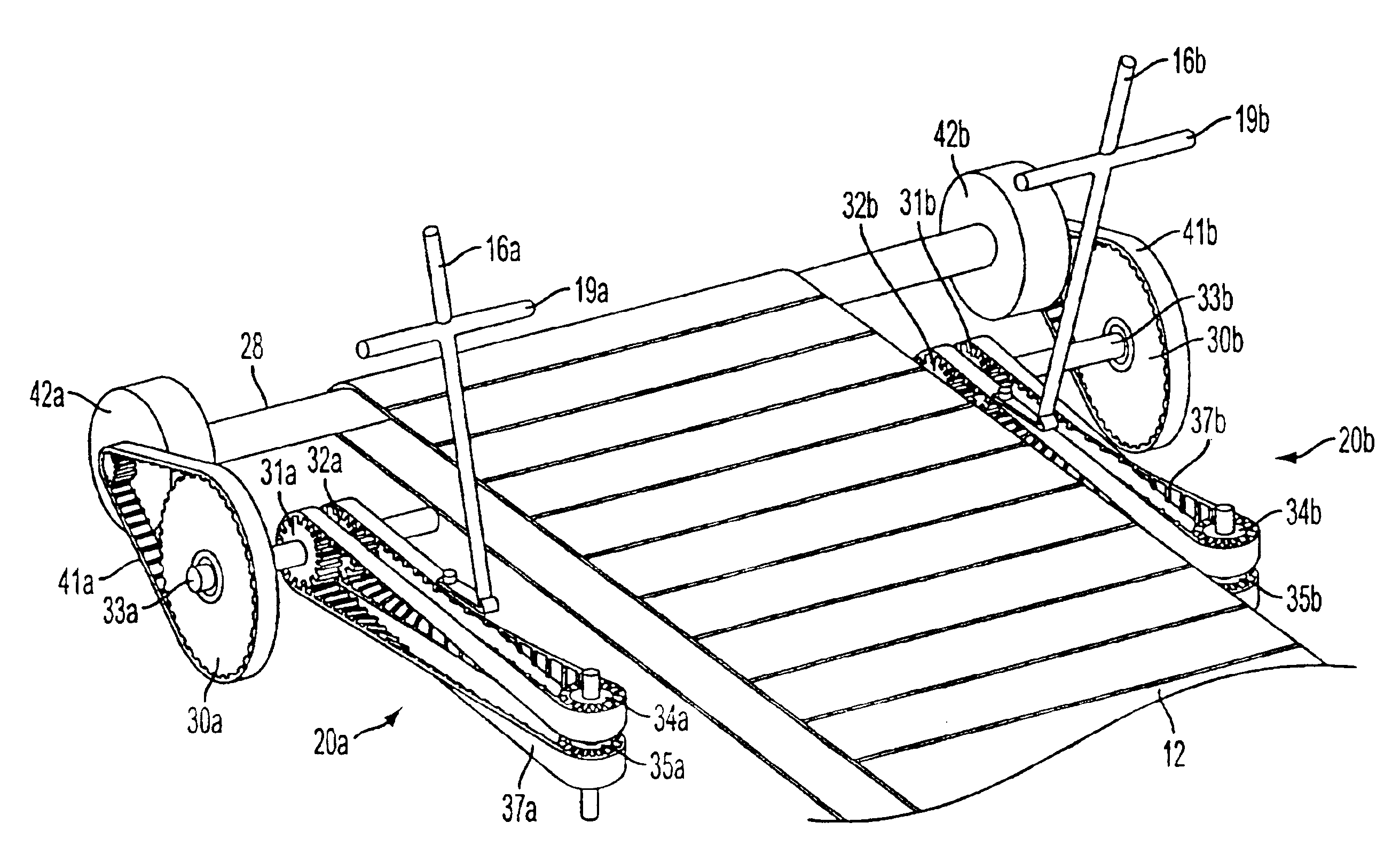
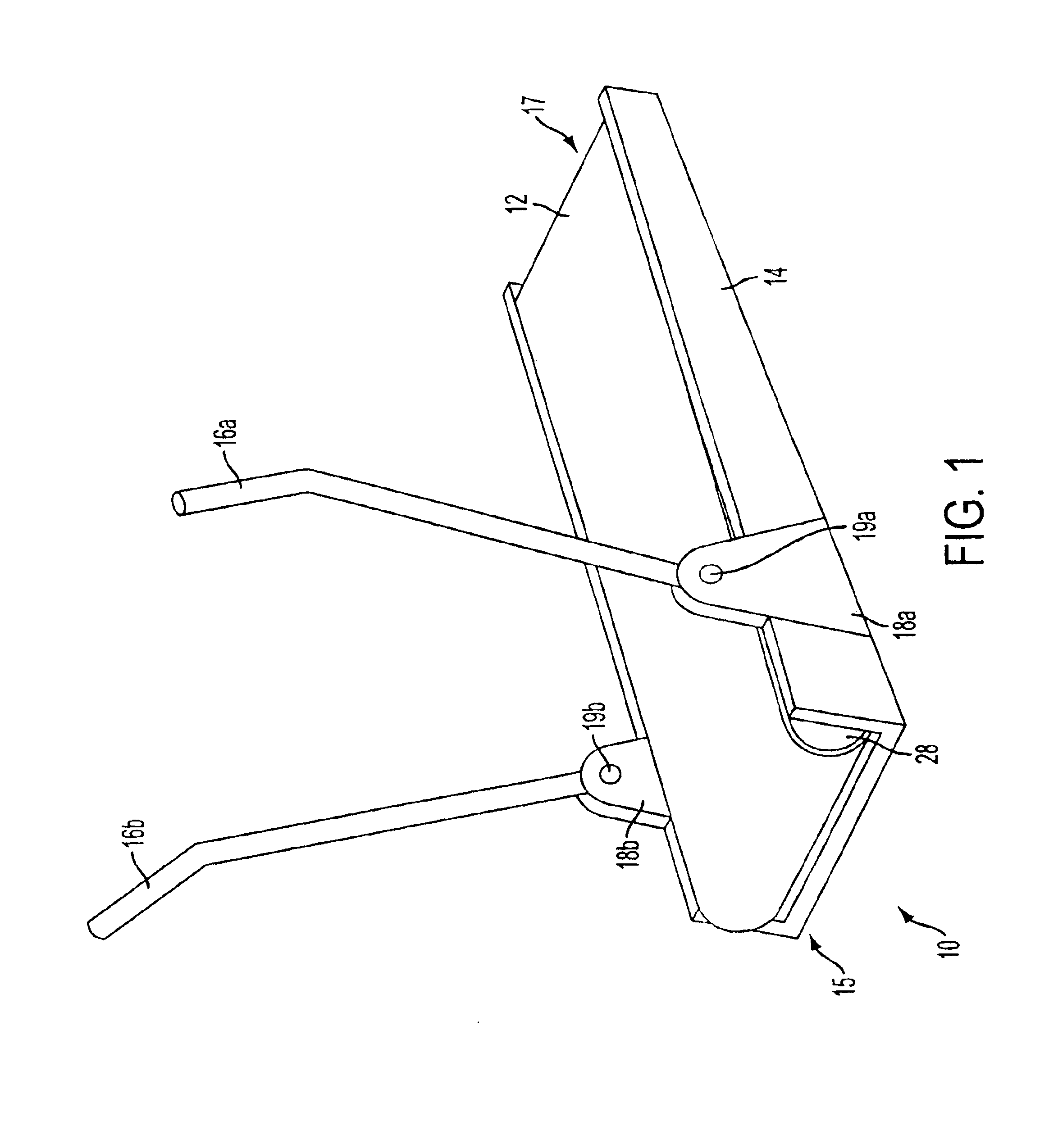
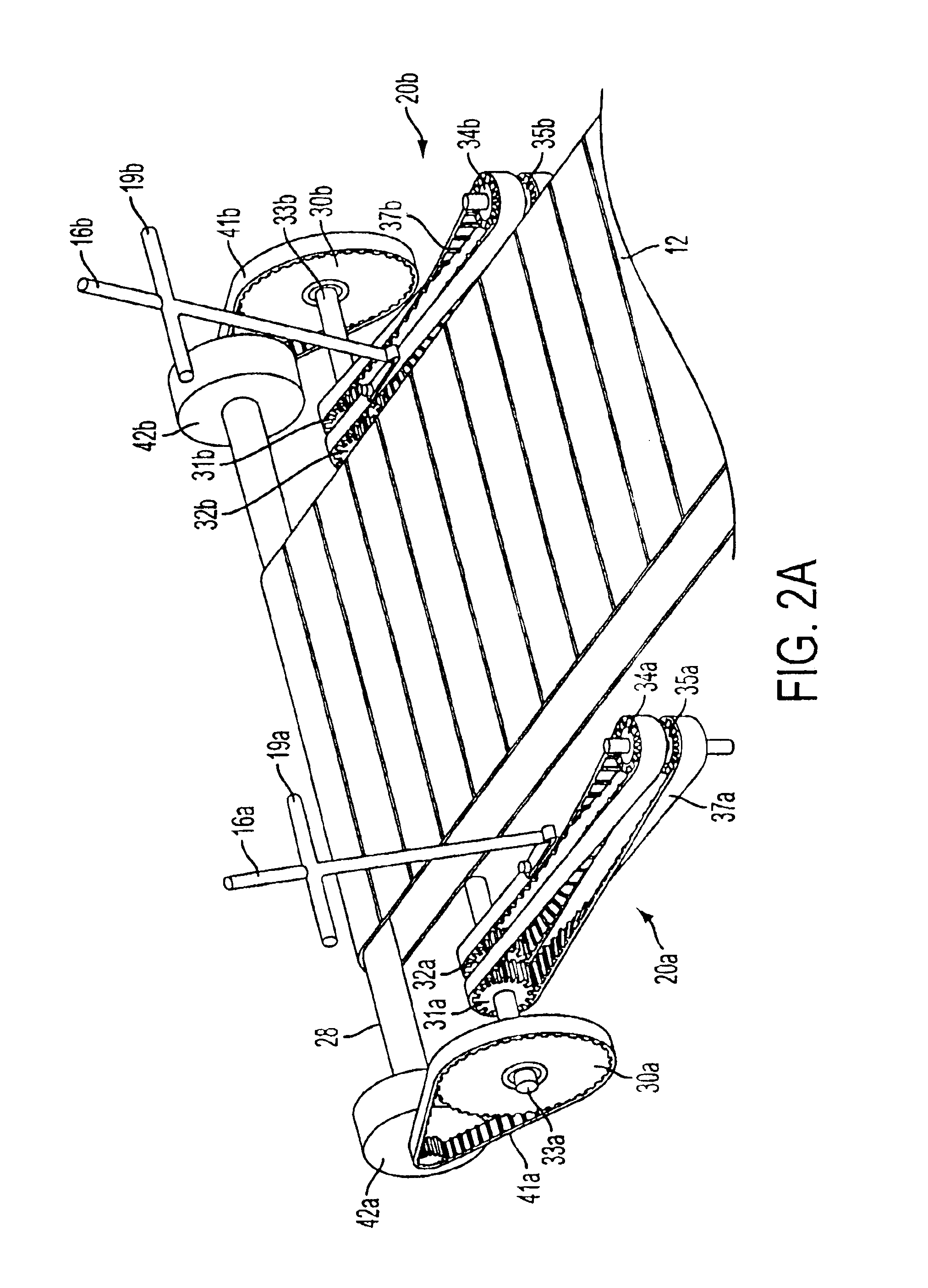
[0023]Referring to the drawings, the preferred embodiment of the manual treadmill of the present invention is illustrated and generally indicated as 10 in FIG. 1. As shown in FIGS. 1, 2a and 2b, treadmill 10 comprises an endless belt 12 riding upon a low-friction support surface (not shown) supported by a base 14. The base 14 is slightly elevated at its forward end 15 with respect to its rearward end 17 such that treadmill 10 is inclined at a relatively shallow angle relative to a level surface. Of course, if desired, treadmill 10 may be arranged such that the incline may be varied by any suitable means, such as by providing manually or automatically adjustable feet or framing members, including pneumatic or hydraulic actuators, or motor-driven incline means. For example, one suitable motor driven elevation means that operates by raising the base of the treadmill with respect to an underlying frame member is described in U.S. Pat. No. 5,462,504, incorporated herein by reference in i...


PUM


Abstract

A motorless treadmill is disclosed which exercises the upper body and lower body of a user. Displacement of an upper-body exercise mechanism such as a pair of reciprocating arm members rotates a drive roller, which is coupled to an endless belt through a transmission system. The transmission system employs a double-wound belt, which links the drive roller to the upper body exercise mechanism such that arm movements are translated into belt rotation. The double-wound belt allows for arm motion in both directions to directly drive the belt, through the use of one-way clutches orientated in opposite directions on the drive shaft. Further, the double-wound belt transmission system allows independent operation of each arm. A flywheel may be added to store energy to smooth the belt rotation.

Description

CROSS REFERENCE TO RELATED APPLICATIONS[0001]This application is a continuation-in-part of, and claims priority to, U.S. patent application Ser. No. 09 / 252,753 filed Feb. 19, 1999, now abandoned, the entire disclosure of which is herein incorporated by reference. Now abandoned.BACKGROUND OF THE INVENTION[0002]1. Field of the Invention[0003]The invention relates generally to exercise equipment, and more particularly to a treadmill for exercising the upper and lower body of a user. More specifically, the present invention relates to a motorless treadmill powered by arm members that move at rates independent of each other.[0004]2. Prior Art[0005]Treadmills for providing a striding or walking exercise surface are well known in the art. Conventional treadmills employ a motor to rearwardly drive an endless belt as a user maintains a striding motion on the exercise surface. Generally, the user of a conventional treadmill is able to vary the speed and incline of the treadmill to obtain a de...

Claims


Application Information

Patent Timeline
IPC IPC(8): A63B22/00A63B22/02A63B21/00A63B21/22A63B23/035
CPCA63B21/154A63B21/157A63B22/02A63B22/001A63B21/225A63B2225/30A63B2022/0041A63B2069/0033
Inventor MOON, DANGOLDFADER, STANLEY
Owner TRUE FITNESS TECH
Learn More