Drivetrain arrangement and method for operating a drivetrain arrangement

a technology of drivetrain and drivetrain, which is applied in the direction of electric propulsion mounting, hybrid vehicles, transportation and packaging, etc., can solve the problem of high friction loading of the frictional shift elemen

Inactive Publication Date: 2008-01-03
ZF FRIEDRICHSHAFEN AG
View PDF3 Cites 46 Cited by
  • Summary
  • Abstract
  • Description
  • Claims
  • Application Information

AI Technical Summary

Benefits of technology

[0025]A further embodiment of the inventive method provides that the frictional shift element of the shift element device, between the electric motor and the combustion engine, is disengaged during a combustion engine powered starting process and the shift element device, between the electric motor and the combustion engine, is engaged. Then, the drive torque, produced by the combustion engine, is passed by the hydraulic coupling element towards the drive output, while the frictional shift element of the shift element device, between the combustion engine and the electric motor, and the shift element device, between the electric motor and the drive output, can be operated without slip and, therefore, almost with no load.
[0026]In a further embodiment of the inventive method, for operating a drivetrain arrangement, the transmission capacity of the frictional shift element of the shift element device, between the combustion engine and the electric motor, is varied in an operating-condition-dependent manner during driving operation in which at least part of a required drive torque is delivered by the combustion engine and the shift element device, between the electric motor and the drive output, is disengaged so that the frictional shift element can be assigned the function of a so-termed converter bridging clutch and the hydraulic effect of the hydraulic coupling element on the drive behavior of the drivetrain arrangement can be varied depending on the operating situation.
[0027]During so-termed recuperative operation, a further embodiment of the inventive method is provided where the frictional shift element of the shift element device, between the combustion engine and the e

Problems solved by technology

In this, the drive torque of the combustion engine is passed through the hydraulic coupling element, with a speed-dependent characteristic, in the direction of the drive output without having to operate th

Method used


Image

  • Drivetrain arrangement and method for operating a drivetrain arrangement
  • Drivetrain arrangement and method for operating a drivetrain arrangement
  • Drivetrain arrangement and method for operating a drivetrain arrangement

Examples


second embodiment

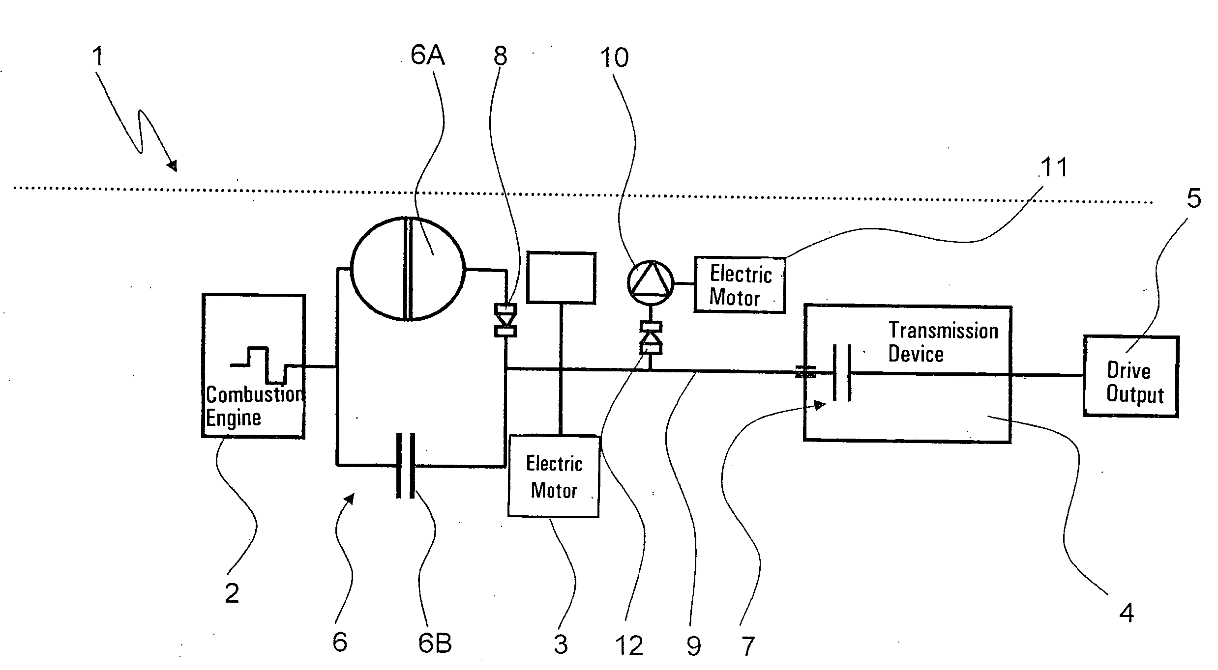
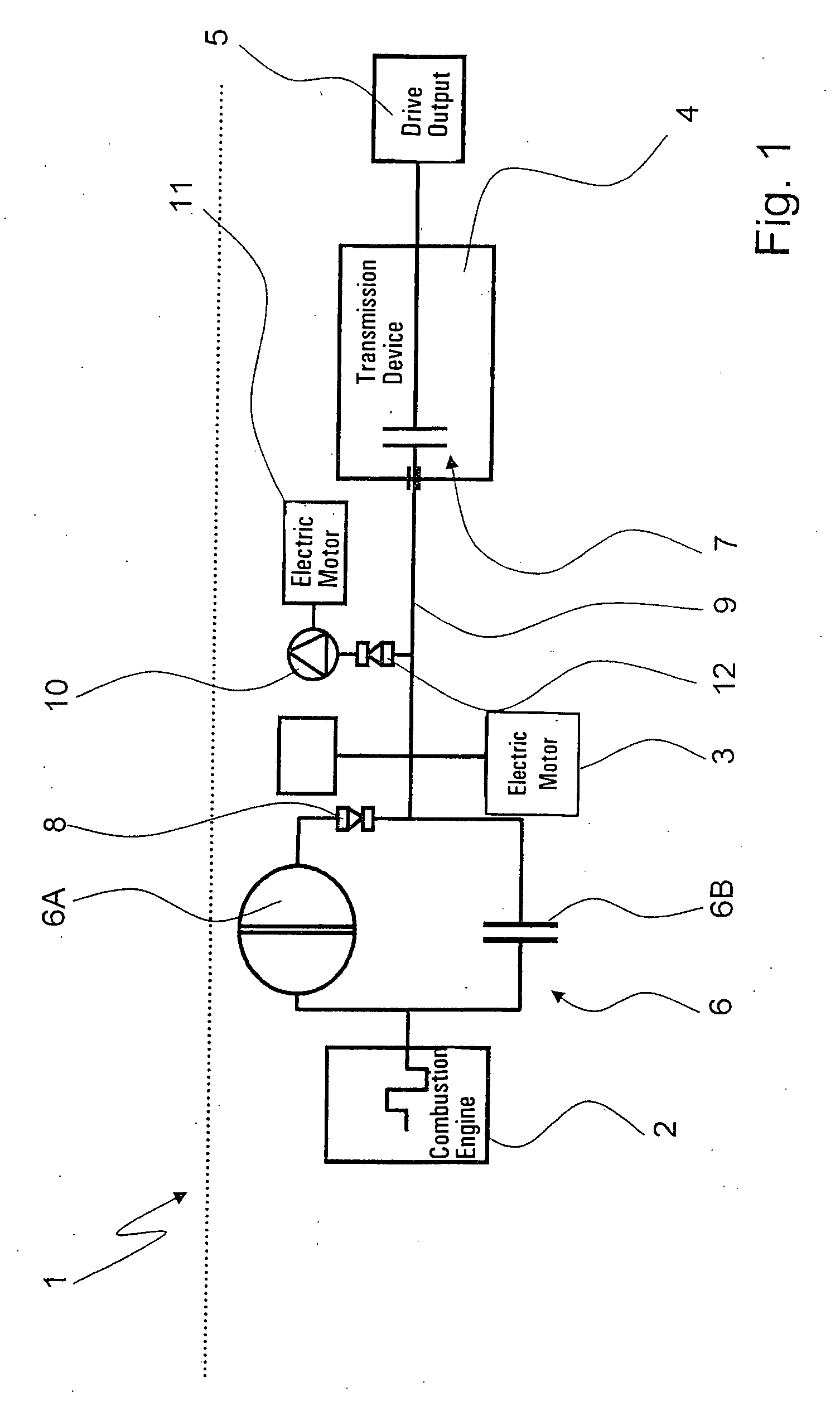
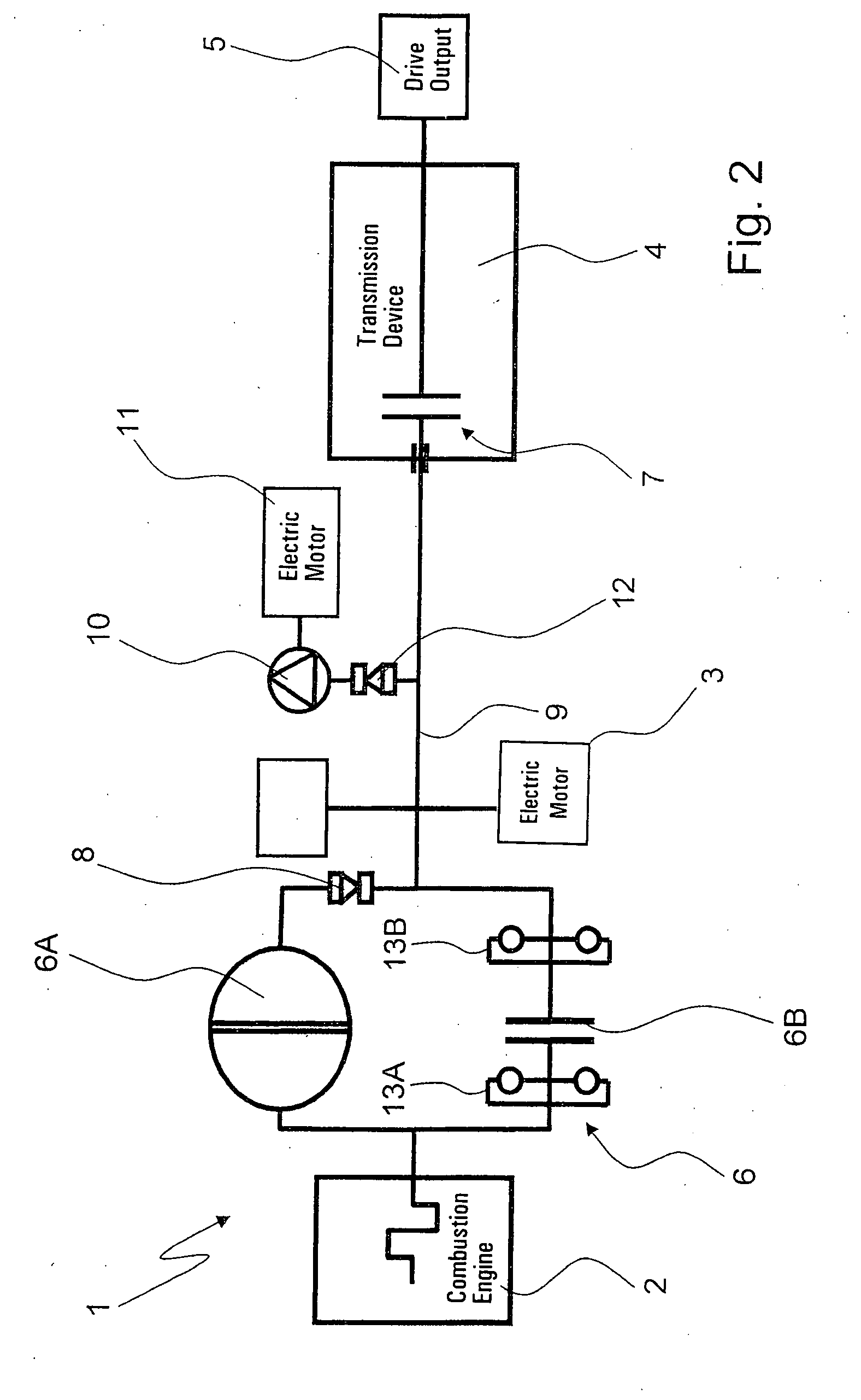
[0047]FIG. 2 shows the parallel hybrid drivetrain 1 of a hybrid vehicle in the form of a block diagram representation, the parallel hybrid drivetrain 1 of FIG. 2 differs from the parallel hybrid drivetrain shown in FIG. 1 essentially only in the area of the shift element device 6, between the combustion engine 2 and the electric motor 3, so that the description which follows will concern only the differences between the two embodiments.

[0048]In the spans between the combustion engine 2 and the frictional shift element 6B and between the frictional shift element 6B and the electric motor 3, the parallel hybrid drivetrain 1 of FIG. 2 contains, in each case, a torsion damper 13A, 13B for damping rotation irregularities in the power path of the parallel hybrid drivetrain 1 such that, in further embodiments of the inventive parallel hybrid drivetrain (not specifically illustrated), it is provided that at least one torsion damper for damping rotation irregularities is arranged between the...

third embodiment

[0050]the inventive parallel hybrid drivetrain 1 is shown in FIG. 3 such that in this embodiment the main transmission pump device 10 can only be driven by the transmission input shaft 9 and a further pump device 14 is associated with the transmission device 4 to deliver pressure to the shift elements of the transmission device 4 while the main transmission pump device 10 is not delivering.

[0051]Moreover, the shift element device 7, between the electric motor 3 and the drive output 5, is made as a frictional shift element located upstream from the transmission device 4, which is arranged in a structural space surrounded by the electric motor.

[0052]In contrast to the transmission-internal configuration of the shift element device 7, between the electric motor 3 and the drive output 5, the transmission-external arrangement of the shift element device 7 is subject to less restrictions in relation to its design as a slipping clutch during a starting process of the combustion engine and,...

fourth embodiment

[0054]As the parallel hybrid drivetrain 1 of FIG. 1, the fourth embodiment is made with an electrically driven main transmission pump device 10, shown in FIG. 4, which is in active connection with the transmission input shaft 9, via the further free-wheel overrunning connection 12. Furthermore, in the same way as the parallel hybrid drivetrain of FIG. 3, according to FIG. 4, the parallel hybrid drivetrain 1 is made with the transmission-externally arranged shift element device 7, between the electric motor 3 and the output drive 5. In addition, a torsion damper 16 for rotation irregularity damping is associated with the electric motor 3, where the driving comfort can be further improved.

[0055]A fifth embodiment of a parallel hybrid drivetrain or drivetrain arrangement 1 made in accordance with the invention, shown in FIG. 5, differs from the fourth embodiment, shown in FIG. 4, essentially in that the shift element device 7, between the electric motor 3 and the drive output 5, is mad...


PUM


Abstract

A vehicular parallel hybrid drivetrain contains a combustion engine, electric motor and drive output and a method of operating the drivetrain. A respective shift element device (6, 7) with continuously variable transmission capacity is provided, between the combustion engine and the electric motor and between the electric motor and the drive. The shift element device (6), between the combustion engine and electric motor, comprises a speed-dependent hydraulic coupling element and a frictional shift element in a parallel power branch. The shift element device (6) has continuously adjustable transmission capacity and is bridged, via the hydraulic coupling element. The hydraulic coupling element actively couples with the electric motor, via a free-wheel overrunning connection (8). This coupling disengages when the speed of the coupling element side of the coupling element is lower than the speed of the electric motor in the area of the free-wheel overrunning connection.

Description

[0001]This application claims priority from German Application Serial No. 10 2006 030 040.8 filed Jun. 29, 2006.FIELD OF THE INVENTION[0002]The invention concerns a drivetrain arrangement and a method for operating a drivetrain arrangement.BACKGROUND OF THE INVENTION[0003]Vehicles known from common practice that have drivetrain arrangements, such as parallel hybrid drivetrains, are usually formed with a shift element mechanism, such made as a frictional clutch, arranged between a combustion engine and the drive output of the vehicle in order to be able to start up the vehicle by way of the combustion engine in a known manner. The starting element is at first operated in a slipping mode during a start-off process. When starting off solely by way of an electric motor of a hybrid vehicle, there is no need for the controlled and regulated slipping operation of the starting element since, in contrast to conventional combustion engines, electric motors have no minimum rotation speed.[0004...

Claims


Application Information

Patent Timeline
IPC IPC(8): B60W10/02F16D45/00
CPCB60K6/387B60K6/48B60K6/547B60K2001/003B60W10/02Y10T477/26B60W10/08B60W10/30B60W20/00B60W2710/025Y02T10/6221B60W10/026Y02T10/62B60W20/40
Inventor SCHIELE, PETERGIERER, GEORGPOPP, CHRISTIAN
Owner ZF FRIEDRICHSHAFEN AG
Why Eureka
Try Eureka