Method and device for stacking flat mailings

a flat mailing and mailing technology, applied in the direction of thin material handling, instruments, sorting, etc., can solve the problems of not being able to react to the individually detected mailings and not being optimal for all types of mailings, and achieve the effect of high friction loading

Inactive Publication Date: 2006-07-04
SIEMENS AG
View PDF12 Cites 1 Cited by
  • Summary
  • Abstract
  • Description
  • Claims
  • Application Information

AI Technical Summary

Benefits of technology

[0020]In order that, in the event of a pause in the supply of mailings, the last mailing is not subjected for too long to a high friction loading on the rotating stacking roll and the moving stacking belt and possibly damaged as a result, the control unit is advantageously designed such that, if a defined time interval is overshot within which no mailings are led into the stacking compartment, the underfloor belt with the part stack held by the stack support is moved away from the stacking roll and the stacking belt until the measured values of the force sensors are so low that the rotating stacking roll and the moving stacking belt do not damage the last mailing. Shortly before the next mailing enters the stacking compartment, the underfloor belt with the part stack is moved toward the stacking roll until the defined stacking forces are reached again.

Problems solved by technology

It is not able to react to the individually detected specifically different mailings.
Thus, for all the different types of mailing, there is only a single stacking force within the stack, which is not optimal for all types of mailing.

Method used


Image

  • Method and device for stacking flat mailings
  • Method and device for stacking flat mailings
  • Method and device for stacking flat mailings

Examples


Embodiment Construction

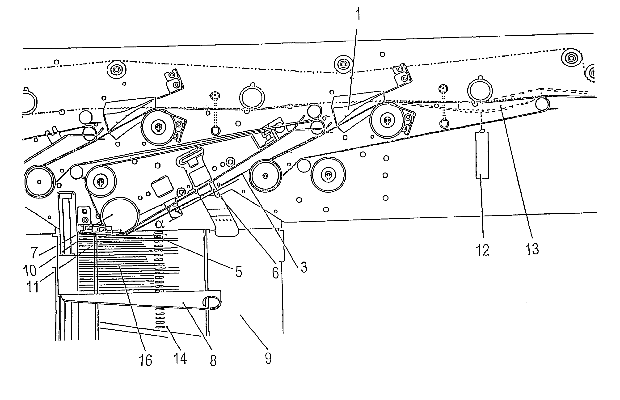
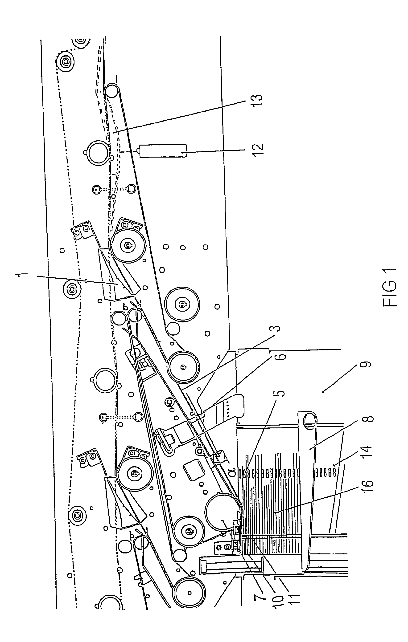
[0024]A stack 16 is formed in that, at the inlet to a stacking compartment 9, in each case a following mailing strikes the preceding mailing at an angle α and slides on said mailing as far as a stop 10, by means of which it is stopped.

[0025]Between a stacking roll 7 and the stack 16 there are forces which have to be overcome by a mailing to be stacked in order to reach the stop 10.

[0026]Arranged in front of the stacking device, in the course of the letters, is a thickness sensor 12, which measures the mailing thickness of the mailing 13 that has just moved past. If the mailing 13 is deflected into the stacking compartment 9 with the aid of a diverter 1, an underfloor belt 14, which has a releasable form-fitting connection to a stack support 8, is moved a certain distance away by a control drive (on the basis of the measured mailing thickness). Thus, sufficient space is created between the stacking roll 7 and the mailing 6 already stacked, into which space it is possible to push the ...


PUM


Abstract

The present invention relates to a method and a device for stacking flat mailings, in which the thickness of each individually conveyed mailing that is to be stacked is detected within a main control loop. The underfloor belt is displaced away from the stacking location by a distance that corresponds to the measured thickness minus a specific distance by means of a stack support for the arriving mailing. The stacking force is measured at different heights in the area of the stacking roll in a static correcting control loop and is re-regulated by moving the underfloor belt within set point values established for the allowed stacking force ranges once each mailing has reached the stop.

Description

CROSS REFERENCE TO RELATED APPLICATIONS[0001]The present application is a continuation of international application PCT / DE03 / 01339, filed on Apr. 24, 2003, which designated the United States and was pending at the time of designation and the filing of the present application; and further claims priority to German patent application 10223349.7, filed May 25, 2002; the both of which are herein incorporated by reference.BACKGROUND OF THE INVENTION[0002]The present invention relates to a method and a device for stacking flat mailings, the mailings including differences with respect to their format (length, height), their thickness, and their stiffness. Flexible and stiff mailings in large and small formats (e.g.: DIN B4 and small postcards) should be capable of being processed both separately and in a mixture. The mailings of different length, height, thickness and stiffness are transported as individual mailings with a minimum spacing in covering belts and, for the purpose of further p...

Claims


Application Information

Patent Timeline
Patent Type & Authority Patents(United States)
IPC IPC(8): B65H43/04B07C1/18B07C3/02B07C5/00B65H29/66B65H31/06B65H31/18B65H31/24G06K9/00
CPCB65H31/06B65H31/18B65H2701/1916B65H2557/61B65H2557/23B65H2511/10B65H2511/11B65H2511/13B65H2511/15B65H2511/222B65H2513/40B65H2513/53B65H2515/34B65H2220/01B65H2220/02B65H2220/11B65H2220/03B65H2513/52
Inventor LINDENMAYER, BERNDOEXLE, DIETMARSKRDLANT, ROLF-PETER
Owner SIEMENS AG
Why Eureka
Try Eureka