Excepting switching transients, the ID·VDS product in the
power MOSFET remains small, and power dissipation in the switch remains low.
Unfortunately, Schottky diodes have several major disadvantages, one of which is that they exhibit a significant and unwanted off-state leakage current, especially at high temperatures.
Moreover, this leakage exhibits a positive
voltage coefficient of current, so that as leakage increases, power dissipation also increases causing the
Schottky diode to leak more and dissipate more power causing even more heating.
With such
positive feedback, localized heating can cause a hot spot to get hotter and “hog” more of the leakage till the spot reaches such a
high current density that the device fails, a process known as
thermal runaway.
Another
disadvantage of Schottky diodes is the difficulty of integrating them into an IC using conventional
wafer fabrication processes and manufacturing.
Commonly available metals exhibit an excessively
high voltage barrier, i.e. they produce a
voltage drop that is too high.
Conversely, other commonly available metals exhibit a barrier potential that is too low, i.e. they produce too much leakage when used in a
Schottky diode.
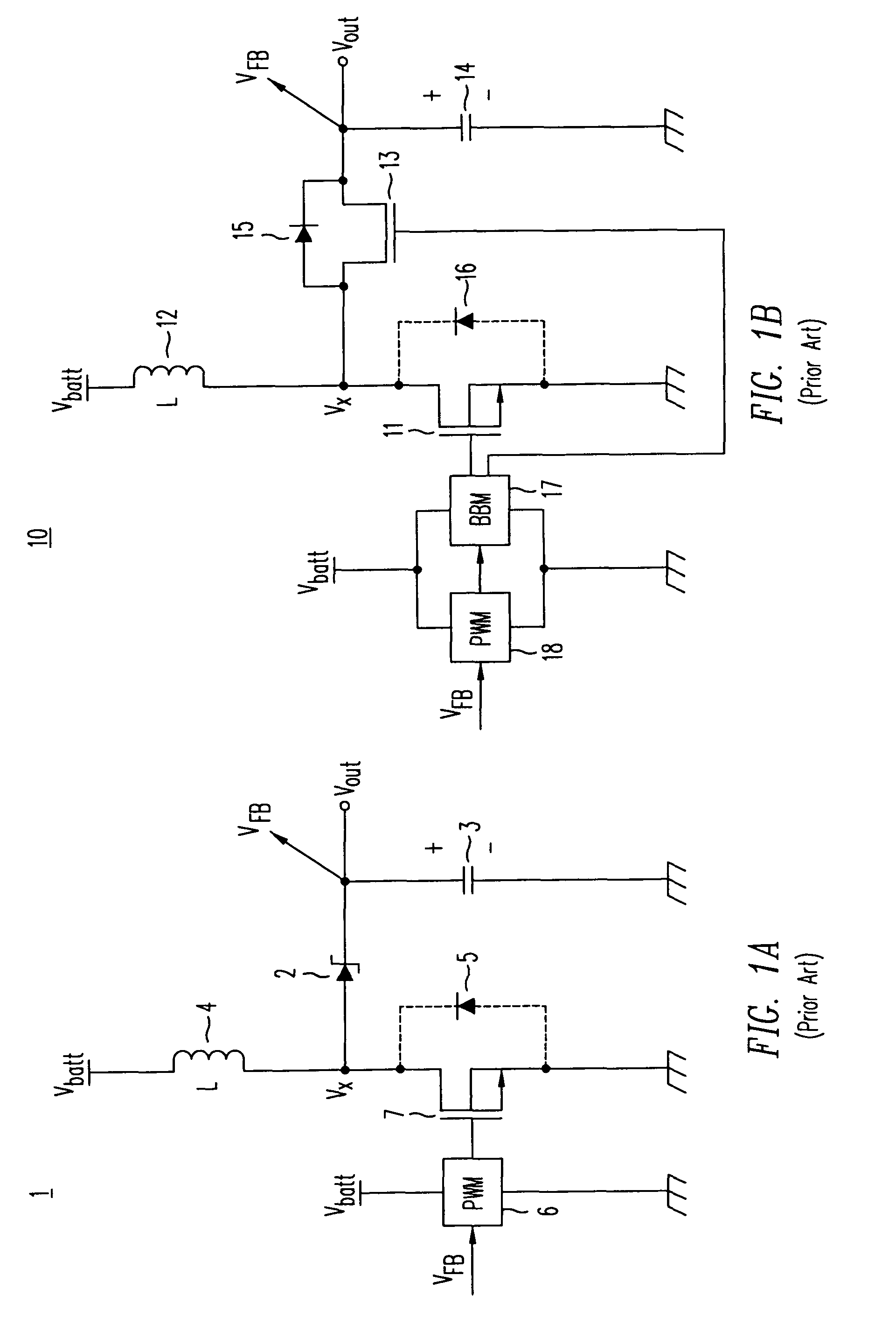
The
synchronous rectifier MOSFET, unlike a Schottky or junction
diode, allows current to flow bi-directionally and the timing of its gate
signal must be precise to prevent
reverse current flow, an unwanted type of conduction that lowers efficiency, increase power dissipation and heating, and may damage the device.
The
disadvantage of transformers is they are large compared to single-winding inductors and suffer from unwanted stray inductances.
Without feedback and closed-
loop control, converter 1 would drive VOUT to an increasingly higher level until
diode 5 goes into
avalanche breakdown, an unwanted and potentially damaging condition.
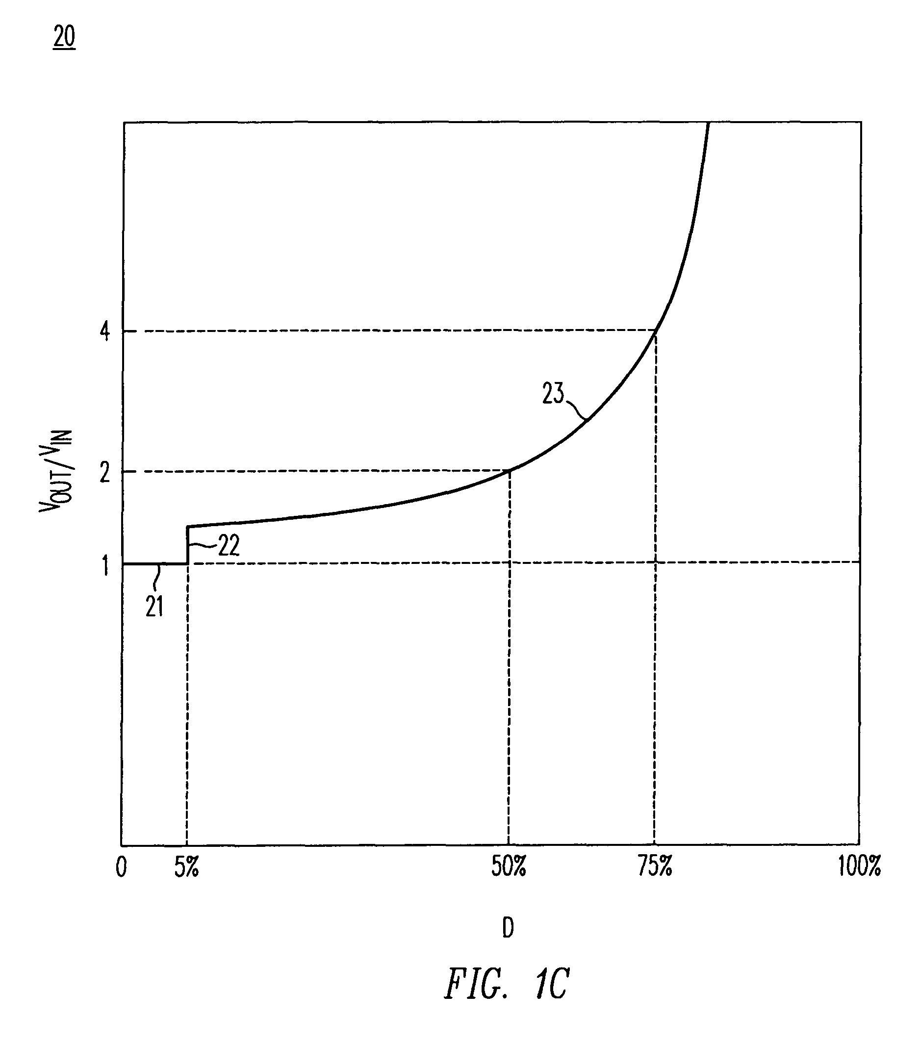
While this equation describes a wide range of conversion ratios, a
boost converter cannot smoothly approach a unity transfer characteristic without requiring extremely fast devices and circuit response times. Considering finite break-before-make intervals and non-zero MOSFET rise and fall times, the discontinuity 22 to a unity transfer 21 occurs because there is inadequate time at very low duty factors to react.
These
high current spikes degrade performance and lower converter efficiency.
One major problem arises when this oscillating frequency corresponds to a frequency approaching 20 kHz or below.
Unfortunately, without being able to vary the lowest frequency, the output
capacitor will over charge and its voltage will exceed the specified tolerance range for the output voltage.
Aside from audio susceptibility and audible
noise, other problems occur at very low
current load conditions.
Unwanted
instability and poor dynamic response can result, depending on the selection of the converter's passive elements.
Another major problem with operating the inductor under starved current conditions is its inability to react to rapid load transients.
Since the inductor current is so low, reacting to a sudden change in load current requires
finite time to reestablish current in the inductor.
While it may at first glance appear this diode is an unavoidable consequence of the design and fabrication of the
power MOSFET structure used as the
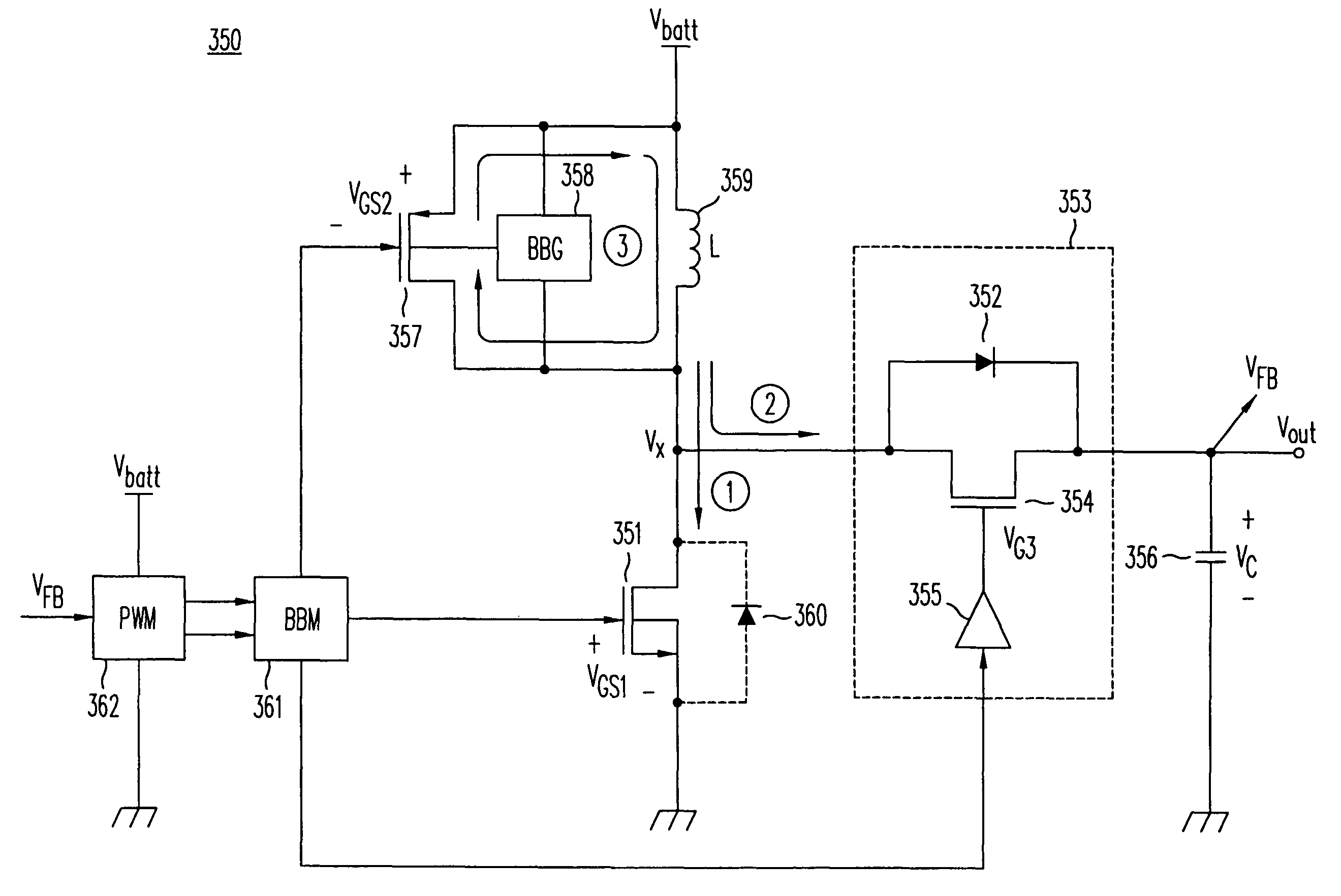
synchronous rectifier, it is in fact an unavoidable and necessary element for synchronous boost converter operation.
If its polarity were reversed, turning on the low-side MOSFET would forward bias the diode and undesirably pull down the output voltage.
Unfortunately, the presence of
rectifier diode 54 limits the output to a voltage greater than Vbatt, making it difficult to regulate an output voltage near the input voltage whenever VOUT≈Vbatt.
Another major problem with the conventional boost or synchronous boost converter occurs at startup.
This problem is especially severe when Vbatt is at its minimum condition when the resistance of MOSFET 51 is higher and unable to establish adequate current in inductor 52.
Overshoot can cause
instability, oscillations and possibly damage load 56.
And since the load current of load 56 is not known and may vary, there is no way to insure reliable startup without the risk of an output voltage that is too high.
In addition to the fact that the energy was lost, dissipated as heat in diode 137, there is a good chance that MOSFET 131 may be damaged or destroyed from the high currents, voltages, and temperature present simultaneously during the UIS transient.
In other words, despite the limitations imposed by the
rectifier diode in a synchronous boost converter, there is no simple way to remove it from prior art circuit topologies without causing UIS related problems and efficiency loss.
Prior art boost and synchronous boost switching regulators both suffer from numerous limitations intrinsic to their circuit topology adversely affecting efficiency,
noise, stability, transient capability and more.
These problems include undesirable variable frequency operation, audio
noise, the need for current reversal detection circuitry, unwanted oscillations when turning off the synchronous rectifier MOSFET to prevent current reversal, poor transient regulation in
light load operation, and the inability to regulate at low-duty-factor and unity voltage conversion ratios.
Especially problematic is the fact that the inductor current,
operating frequency, and converter stability are particularly sensitive to the load current and the complex equivalent impedance of the load being powered by the boost converter.
Achieving reliable start-up into a full load current from a
low input voltage greatly limits prior art step-up
converters.
Over-magnetizing the inductor creates a problem of
overvoltage conditions on the output that may damage the converter's load.
Eliminating the rectifier diode to achieve step-down operation or to improve startup by unloading the circuit creates additional and even greater problems due to unclamped inductive switching, noise, efficiency loss and potential device damage.

