Display apparatus having snap pin reinforcing member fastening mechanism

a technology of reinforcing member and fastening mechanism, which is applied in the direction of electrical apparatus casing/cabinet/drawer, identification means, instruments, etc., can solve the problems of inconvenient high material cost, and inconvenient disassembly and assembly of display apparatus, etc., and achieves slim and compact appearance, easy disassembly and assembly in a relatively short period of tim

Inactive Publication Date: 2005-05-17
SAMSUNG ELECTRONICS CO LTD
View PDF20 Cites 86 Cited by
  • Summary
  • Abstract
  • Description
  • Claims
  • Application Information

AI Technical Summary

Benefits of technology

[0015]Accordingly, it is an object of the present invention to provide a display apparatus which can be

Problems solved by technology

However, the conventional display apparatus employs screws to connect the front cover 112 and the rear cover 127 as well as the front cover 112 and the panel supporting member 142, so that it is inconvenient to assemble the display apparatus.
Further, in the conventional display apparatus, the PCB cover 146, accommodating the PCB assemb

Method used


Image

  • Display apparatus having snap pin reinforcing member fastening mechanism
  • Display apparatus having snap pin reinforcing member fastening mechanism
  • Display apparatus having snap pin reinforcing member fastening mechanism

Examples


Embodiment Construction

[0035]Reference will now be made in detail to the embodiments of the present invention, examples of which are illustrated in the accompanying drawings, wherein like reference numerals refer to like elements throughout. The embodiments are described below in order to explain the present invention by referring to the figures.

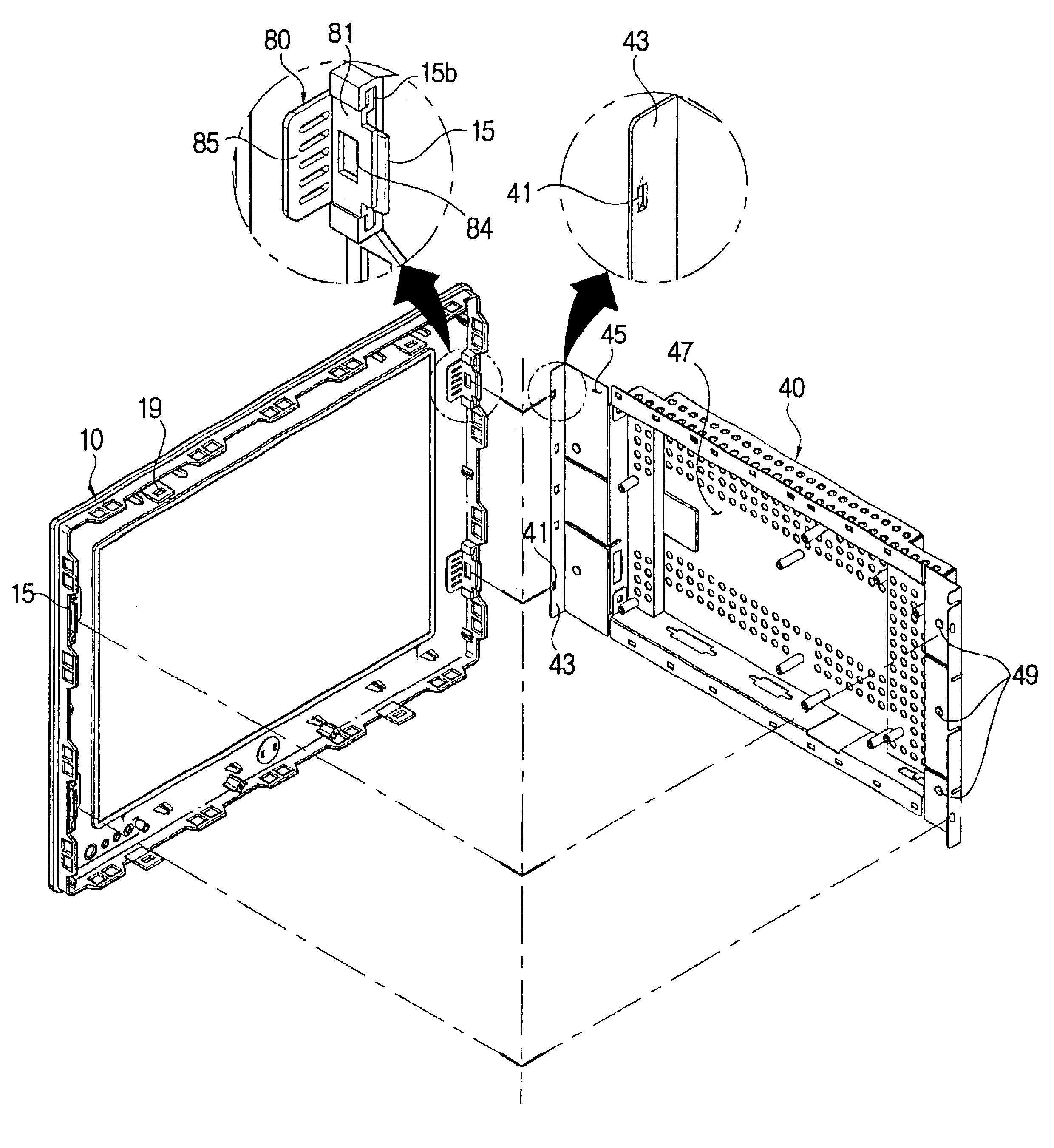
[0036]As illustrated in FIGS. 3 through 6, a display apparatus according to an embodiment of the present invention comprises an LCD panel 30, a PCB assembly 60 communicating an electric signal with the LCD panel 30, a front cover 10 covering the front edge of the LCD panel 30, a panel supporting member 40 connected to the front cover 10, with the LCD panel 30 and the PCB assembly 60 being disposed therebetween, a rear cover 20 connected to the front cover 10 behind the panel supporting member 40, and a stand 70 supporting the assembled components 10, 20, 30, 40 and 60.

[0037]The LCD panel 30 displays a picture thereon according to the principle that a molecular arr...


PUM


Abstract

A display apparatus having an LCD panel, a front cover covering a front edge of the LCD panel, a panel supporting member connected to the front cover, with the LCD panel being disposed therebetween, and a rear cover disposed in back of the panel supporting member and connected to the front cover. The display also includes a first snap pin protruding from the rear of the front cover and having a first projection holder, a reinforcing member formed with an opening and having a projection engaging with the first projection holder of the first snap pin, and a flange part formed on the panel supporting member and having a first projection engaging with the opening of the reinforcing member. With this configuration, a display apparatus can be assembled or disassembled in relatively short time, has a slim and compact appearance, and has an improved EMI shielding effect.

Description

CROSS-REFERENCE TO RELATED APPLICATIONS[0001]This application claims the benefit of Korean Application No. 2002-32663, filed Jun. 11, 2002, in the Korean Intellectual Property Office, the disclosure of which is incorporated herein by reference.BACKGROUND OF THE INVENTION[0002]1. Field of the Invention[0003]The present invention relates to a display apparatus, and more particularly, a display apparatus improved in a panel supporting member supporting an LCD (liquid crystal display), a front cover, and a rear cover.[0004]2. Description of the Related Art[0005]As illustrated in FIGS. 1 and 2, a conventional display apparatus comprises a front cover 112 and a rear cover 127 connected to the front cover 112 and forming a predetermined accommodating space, an LCD panel 140 having an effective surface on which a picture is displayed, a panel supporting member 142 supporting the LCD panel 140, and a PCB (printed circuit board) assembly 144 supported by a PCB cover 146 and transmitting an el...

Claims


Application Information

Patent Timeline
IPC IPC(8): G02F1/13G02F1/1333G09F9/00G09F9/35H04N5/64H04N5/645H05K5/02H05K7/12
CPCG02F1/133308G02F2001/13332G02F2201/465G02F2201/36G02F2001/133334G02F1/13332G02F1/133334H04N5/645
Inventor SUNG, KI-HYUBLIM, SEON-WOO
Owner SAMSUNG ELECTRONICS CO LTD
Why Eureka
Try Eureka