Automatic reset target

a target and automatic technology, applied in the field of multiple target devices, can solve the problems of lack of features or simplicity of operation for marksmen, and achieve the effect of convenient attachment and quick positioning

Active Publication Date: 2005-05-24
DO ALL TRAPS
View PDF21 Cites 65 Cited by
  • Summary
  • Abstract
  • Description
  • Claims
  • Application Information

AI Technical Summary

Benefits of technology

[0007]Another object of this invention is to provide a means for continuously shooting at individual targets without the necessity of manually resetting targets to a pre-shot position.
[0008]A further object of this invention is to provide a non-mechanical mechanism that utilizes projectile mom

Problems solved by technology

Automatically resettable targets have been developed in various configurations,

Method used


Image

  • Automatic reset target
  • Automatic reset target
  • Automatic reset target

Examples


Embodiment Construction

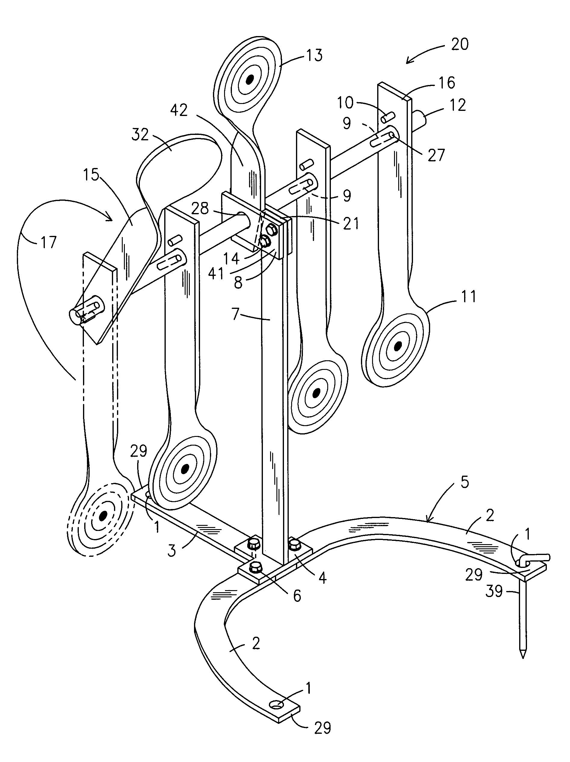
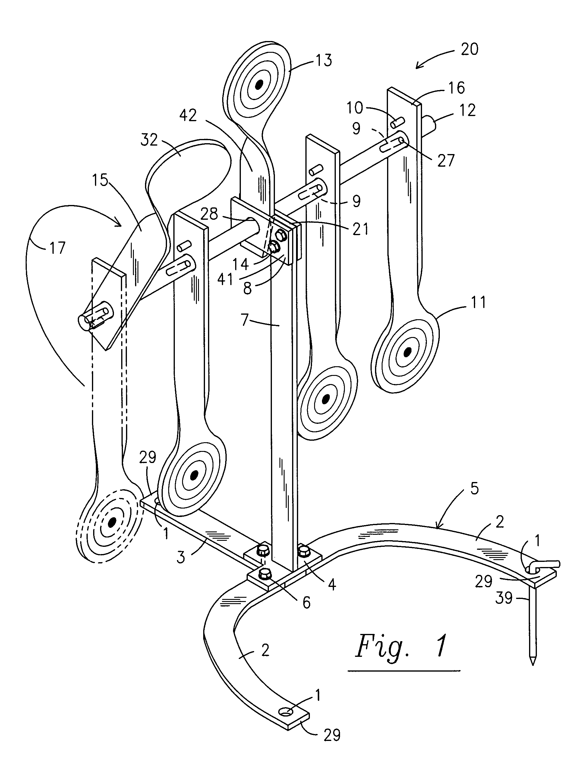
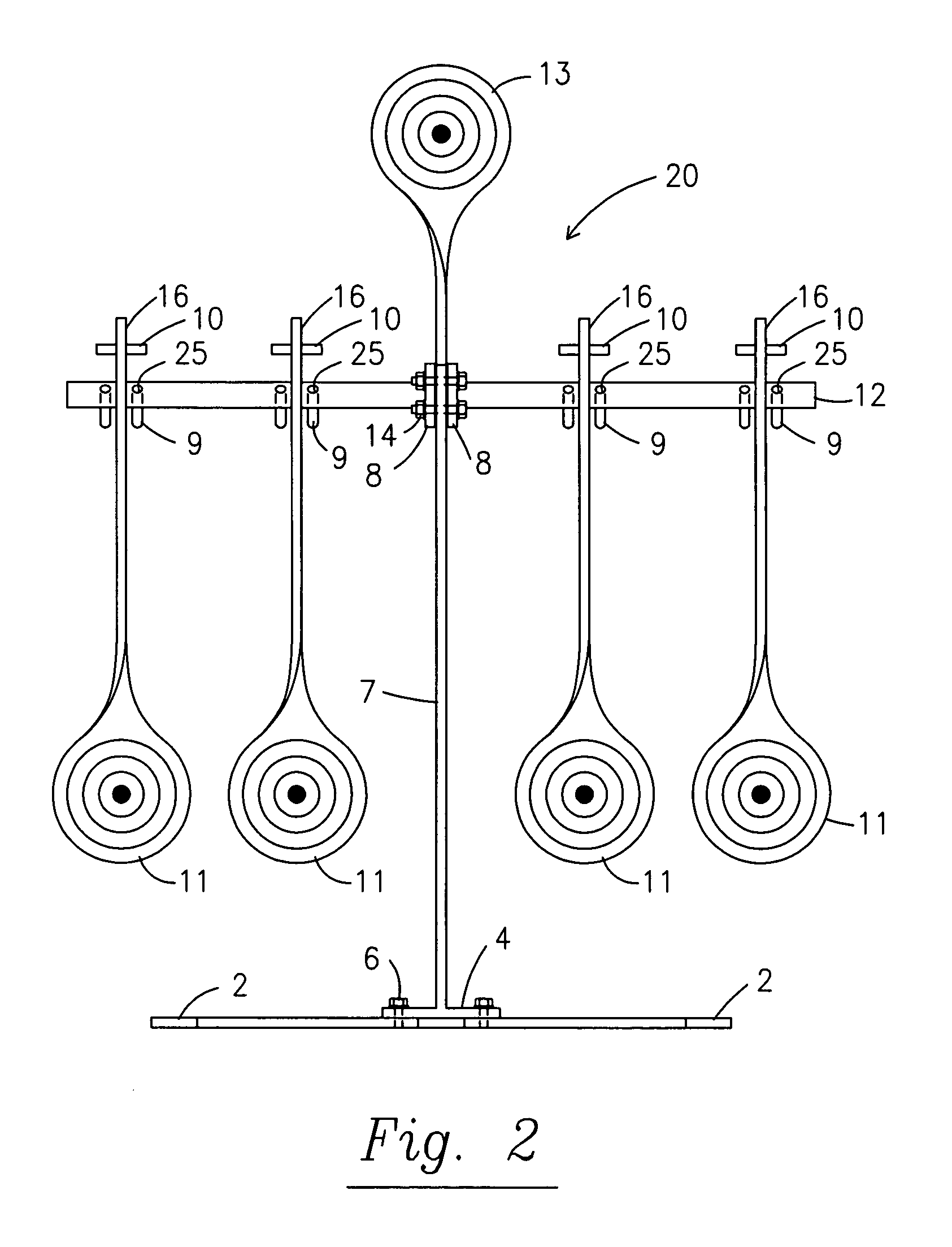
[0019]Turning to FIG. 2, the auto-reset target apparatus 20 is illustrated from a front view revealing the pivotable targets 11 in their downward or pre-shot positions. Pivotable targets 11 are preferably fabricated from metal or similar material to be resistant to damage from gun fire. Different thicknesses and hardnesses of metal may be employed depending upon the caliber and velocity of bullets intended for use with the targets. The auto-reset target 20 is supported by a three-pronged base 5 best seen in FIGS. 1 and 4, having two forward legs 2 and one rear leg 3 forming a “Y” shape. The base design is only one of many possible designs appropriate for supporting the target apparatus 20 to prevent undue movement as shots fired at the targets 11,13 tend to rock the target apparatus 20 rearward. Spike holes 1 positioned at the terminal end 29 of each of the three legs 2,3 serve to receive spikes 31 to hold the target apparatus 20 in place when placed on turf. A weighted object such...


PUM


Abstract

A resettable target is provided with pivotable targets that rotate from a downward position to an upward position and are reset by reverse rotation when momentum is transmitted from a projectile to a reset target.

Description

BACKGROUND OF THE INVENTION[0001]This invention generally relates to a multiple target apparatus and, more particularly, to a target apparatus with a plurality of pivotable targets that are meant to rotate or pivot around a central axis from a lower to an upper or prone position from the impact of a bullet or other projectile. The individual targets are then returned to their lower position from the impact of a bullet upon a reset target reversely pivoting and resetting the pivotable targets for continued shooting.[0002]Rifles, pistols and shotguns are used to shoot bullets or similar projectiles at targets both for the practice of marksmanship and in competitions. Characteristics of targets used in these activities generally include clearly visible and easily identifiable areas of desired impact, commonly referred to as bull's-eyes, a means for determining the point of impact of the bullet or projectile, and the ability to change or reset targets. A significant convenience to targe...

Claims


Application Information

Patent Timeline
IPC IPC(8): F41J7/00F41J7/04
CPCF41J7/04
Inventor LE ANNA, DAVID
Owner DO ALL TRAPS
Why Eureka
Try Eureka