

A multi-piston continuous shooting toy gun
A multi-piston, toy gun technology, applied to compressed air guns, weapons without explosives, offensive equipment, etc., can solve the problems that children cannot play and are inconvenient to use, and achieve the effects of high safety and convenient use.
- Summary
- Abstract
- Description
- Claims
- Application Information
AI Technical Summary
Problems solved by technology
Method used
Image

Examples
Embodiment 1
[0034] A multi-piston serial shooting toy gun,
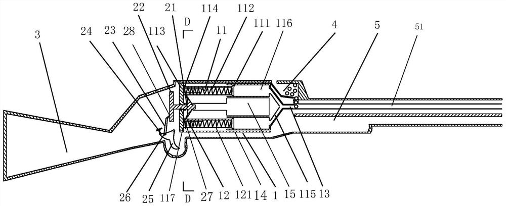
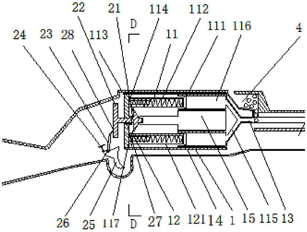
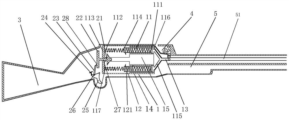
[0035] It includes a gun body 1, a bullet adding ejection mechanism located at the front end of the gun body 1, a pneumatic mechanism located in the middle of the gun body 1 and pushing bullets to be ejected by air pressure, a loading mechanism for accumulating energy for the pneumatic mechanism, and a charging mechanism located in the middle of the gun body 1. The trigger mechanism at the rear of the gun body 1 and used to trigger the pneumatic mechanism to release energy;
[0036] The bullet adding ejection mechanism includes a gun barrel 5 arranged at the front end of the gun body 1, a bullet passage 51 formed in the gun barrel 5 for bullets to be ejected, and a bullet passage 51 located at the top of the gun barrel 5 and connected to the bullet passage 51 through a bullet connecting pipe. The connected magazine 4, wherein the diameters of the bullet connecting pipe and the bullet channel 51 are the same as the diameter of th...
Embodiment 2
[0049] In this embodiment, on the basis of the first embodiment, the pulling bolt is further optimized.
[0050] The pull bolt 6 includes a pull handle 63 arranged outside the body of the gun 1 and a pull bolt front end 64 which is arranged in the body of the gun 1 and cooperates with the slot. A cavity 65 is formed inside the front end 64 of the pull bolt. An opening 66 is formed at the front end of the cavity 65 , the rear end of the bolt head 62 is fixed in the cavity 65 by the telescopic spring 61 , and the front end of the bolt head 62 passes through the opening 66 .
[0051] Way of working:
[0052] The bolt head 62 and the telescopic spring 61 pass through the strip groove 16 and are arranged in the gun body 1 , and the pulling handle 63 is arranged outside the gun body 1 . The bolt head 62 of the pull bolt 6 passes through the slot of the connecting cylinder 14 and is stuck on the clip 114 on the piston 11 . Slide and pull the handle 63 backward, the bolt head 62 dri...
Embodiment 3
[0054] In this embodiment, on the basis of the first embodiment, the pneumatic device is further optimized.
[0055] The piston includes an air plug 111 that is sealingly and slidably connected to the piston channel 116, an air cylinder 121 fixed at the rear of the air plug 111 and a power spring 112, one end of the power spring 112 is fixed on the bottom plate 113, The other end is fixed on the air plug 111 after passing through the air cylinder 121 . The air plug 111 can be made of rubber to improve the sealing performance.
[0056] As a preferred manner, the locking block 12 is fixedly arranged on the side of the rear end of the outer wall of the air cylinder 121 close to the central cylinder 15 . By limiting the position of the air cylinder 121 , it plays a role in defining the position of the air plug 111 .
[0057] As a preferred manner, the front end of the spring bottom plate 113 is fixed with a spring limit block 117, and the spring limit block 117 is coaxially slee...
PUM
 Abstract
Description
Claims
Application Information