
Partial image decompression of a tiled image

a tiled image and image decompression technology, applied in the field of digital imaging, can solve the problems of limited texture mapping processing requirements of professional graphic systems, computer graphic systems generally not designed to process and display spherical surfaces, transmission and storage of environment maps for high resolution flicker-free display may be beyond the processing capabilities of most computer systems

Inactive Publication Date: 2005-05-24
DIGIMEDIA TECH LLC
View PDF25 Cites 37 Cited by
  • Summary
  • Abstract
  • Description
  • Claims
  • Application Information

AI Technical Summary

Benefits of technology

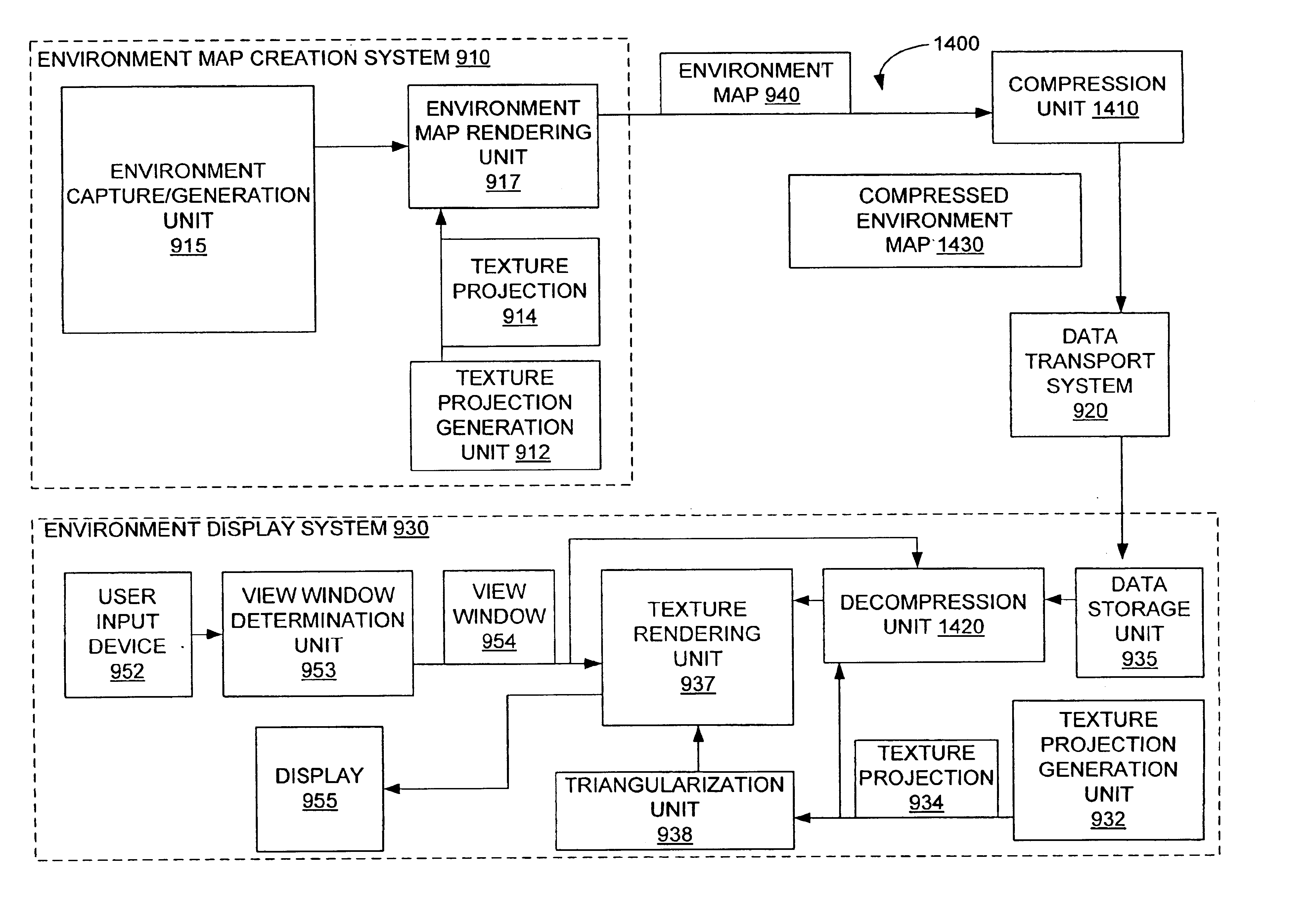
[0023]After decompression of the subset of relevant tiles, an environment display system uses the newly formed decompressed environment map to texture map the view window. Specifically, the environment display system uses a texture projection having polygonal curved surfaces as an object to be texturized using the decompressed environment map. In some em

Problems solved by technology

At one time, the processing requirements of texture mapping limited texture mapping to professional graphic systems.
Computer graphic systems are generally not designed to process and display spherical surfaces.
Difficulties with immersive video are typically caused by the vast amount of data required to create a high resolution environment map and the large number of environment maps required for immersive video.
Specifically, transmission and storage of the environment maps for high resolution flicker-free display may be beyond the processing capabilities of most computer systems.
However, the additional processing time required to decompress a compressed environment map may impair the ability of the environment display system to process an adequate number of environment maps to provide a flicker-free display.
The excessive data problem for immersive video is compounded by the inefficiencies of the conventional texture projections used to form environment maps.
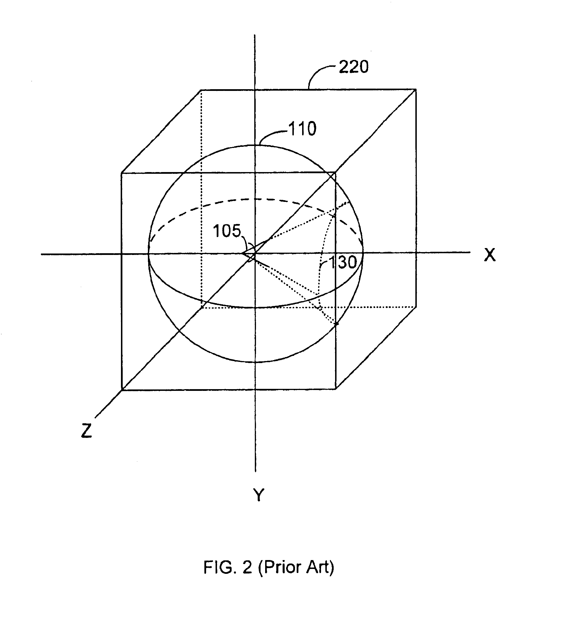
Specifically, although a cubic texture projection can provide realistic environment views, the cubic texture projection is not very efficient, i.e., the average amount of environment information per area is relatively low.
Thus, the mapping of circle 410 to square 420 results in inefficiencies due to the non-uniformity of the mapping.

Method used


Image

  • Partial image decompression of a tiled image
  • Partial image decompression of a tiled image
  • Partial image decompression of a tiled image

Examples


Embodiment Construction

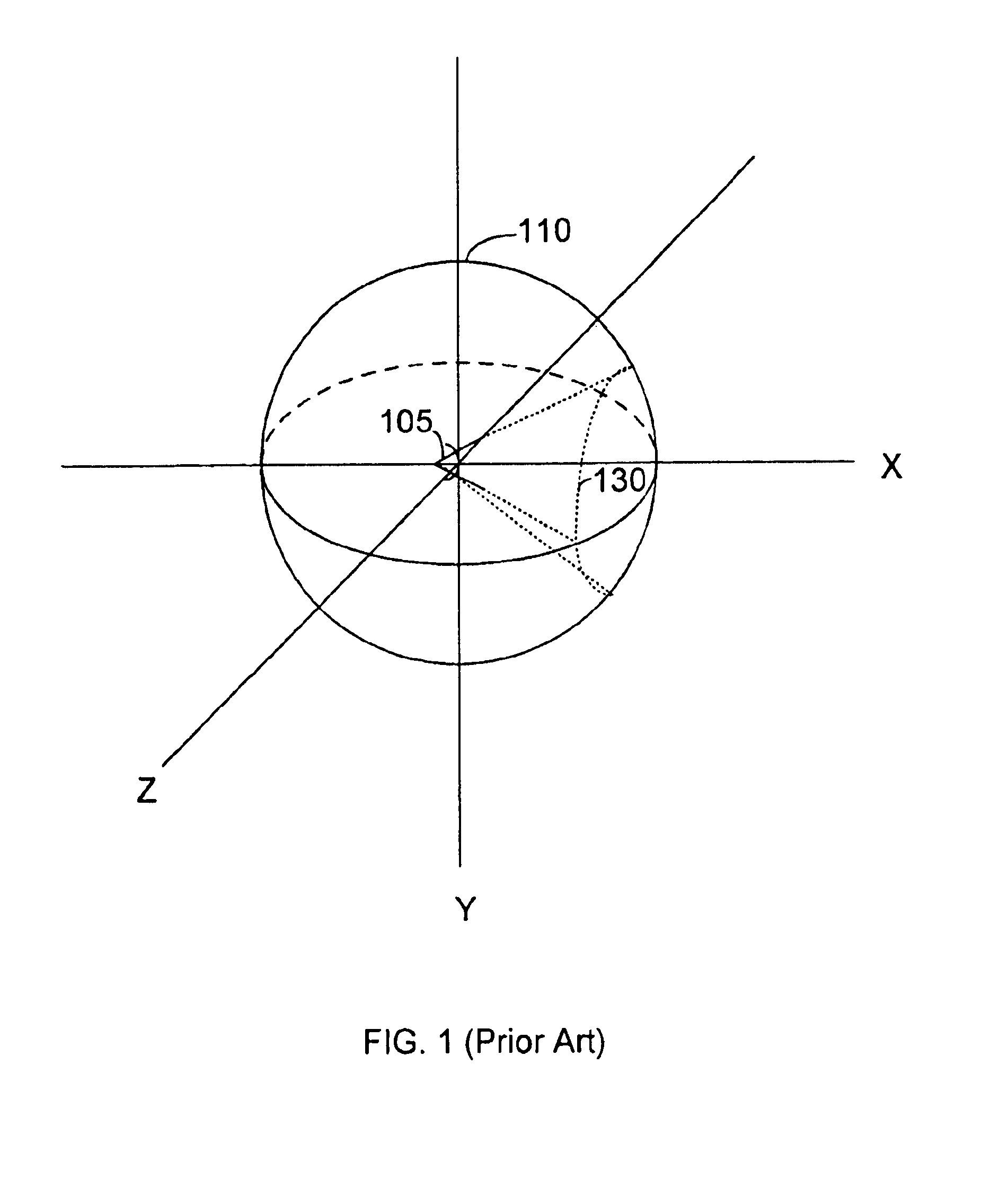
[0046]As explained above, environment mapping typically represents the environment around a user using a sphere. Specifically, the user's view of the environment is represented as a texture map on the inside surface of the sphere. The environment is texture mapped onto the inside surfaces of a solid. Typically, a texture projection is formed by dividing the inner surfaces of the solid into polygonal facets. However, as explained above, conventional texture projections are inefficient as compared to an ideal texture projection. Furthermore, ideal texture projections are impractical because ideal texture projections can use only a limited number of facets.

[0047]The present invention provides texture projections which provide greater efficiency than conventional texture projections by using facets that nearly satisfy the criteria of the facets of an ideal texture projection. Specifically, the facets used in the present invention are polygonal curved surfaces rather than polygons. Polyg...


PUM


Abstract

A decompression unit is configured to partially decompress a compressed image formed by compressed tiles. Each compressed tiles correspond to a tile of the uncompressed image. The decompression unit selects a subset of relevant tiles, which are visible in a view window or a view frustum. Specifically, the decompression unit includes a tile selector to select the relevant tile and a tile decompressor to decompress the relevant tiles. By decompressing only a subset of the compressed tiles, the decompression unit reduces the processing time required to generate the contents of the view window.

Description

CROSS-REFERENCE TO RELATED APPLICATIONS[0001]This application relates to concurrently filed, co-pending application Ser. No. 09 / 505,337, “POLYGONAL CURVATURE MAPPING TO INCREASE TEXTURE EFFICIENCY”, by Hashimoto, et. al., owned by the assignee of this application and incorporated herein by reference.[0002]This application relates to concurrently filed, application Ser. No. 09 / 505,338 (now issued as U.S. Pat. No. 6,559,853), “ENVIRONMENT-MAP CREATION USING TEXTURE PROJECTIONS WITH POLYGONAL CURVED SURFACES”, by Hashimoto, et. al., owned by the assignee of this application and incorporated herein by reference.[0003]This application relates to concurrently filed, co-pending application Ser. No. 09 / 505,442, “ENVIRONMENT DISPLAY USING TEXTURE PROJECTION WITH POLYGONAL CURVED SURFACES”, by Hashimoto, et. al., owned by the assignee of this application and incorporated herein by reference.[0004]This application relates to concurrently filed, co-pending application Ser. No. 09 / 505,334, “IMAG...

Claims


Application Information

Patent Timeline
IPC IPC(8): G06T17/00G06T15/00G06T9/00G09G5/00
CPCG06T9/001H04N19/44H04N19/70
Inventor HASHIMOTO, ROY T.LAVIN, ANDREW J.
Owner DIGIMEDIA TECH LLC
Learn More