
Compressed moving image decompression device and image display device using the same

a technology of moving image and display device, which is applied in the field of compressed moving image decompression device and image display device using the same, can solve the problems of large amount of information, large processing load of quantization and most processing before quantization etc., and achieves small processing load to the software processing section, small number of types of information and information significant, and small operation load of variable-length coding

Inactive Publication Date: 2005-02-10
SEIKO EPSON CORP
View PDF19 Cites 12 Cited by
  • Summary
  • Abstract
  • Description
  • Claims
  • Application Information

AI Technical Summary

Benefits of technology

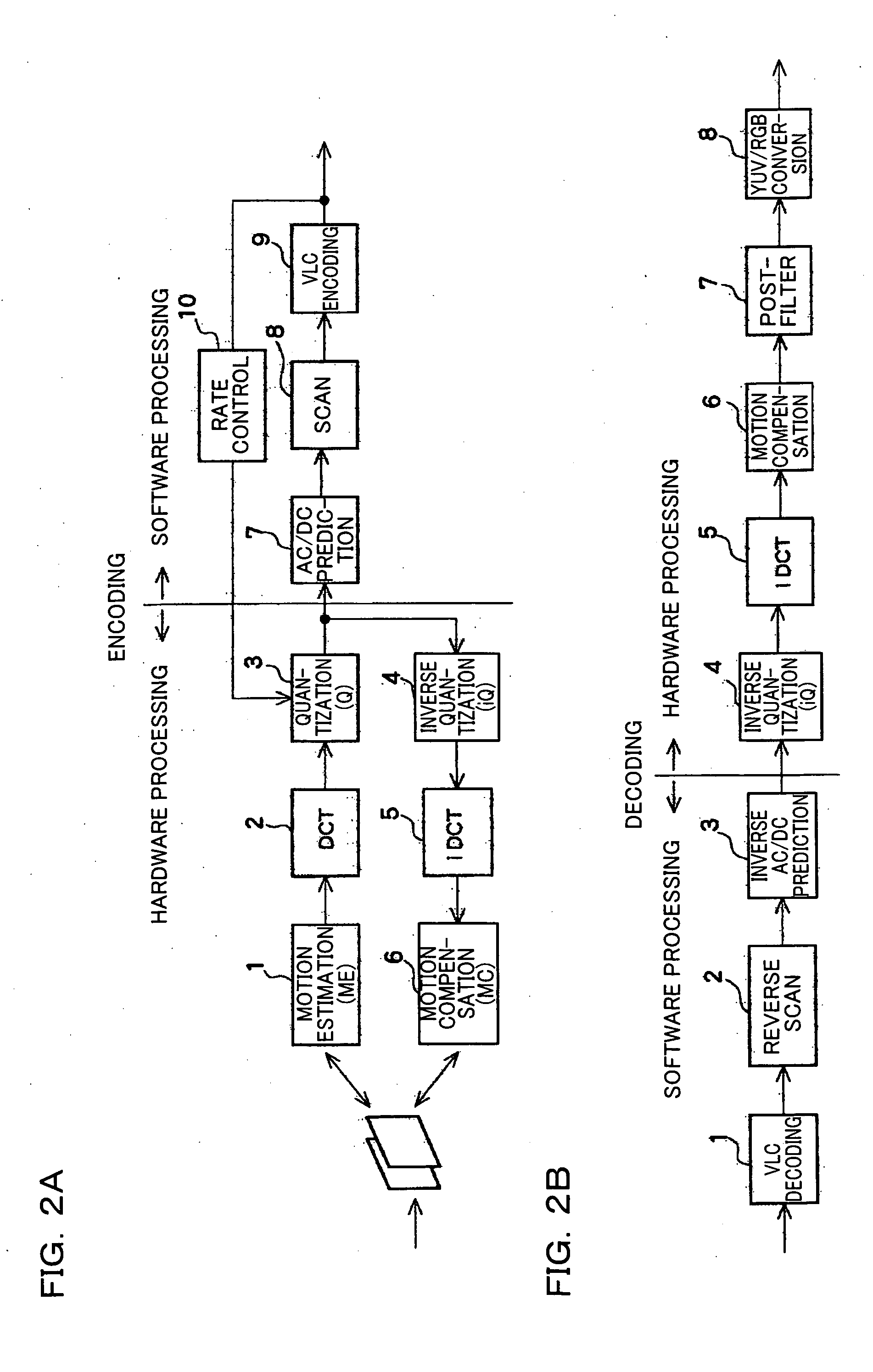
[0014] Most of the moving image data quantized after the discrete cosine transform is zero data, and so the number of types of information and amount of information are significantly small in comparison with the data before quantization. Moreover, the operation load for the variable-length coding is small. Therefore, the processing load to the software processing section is small because the amount of information is small and the operation load is reduced. On the contrary, the processing load of quantization and most processing before the quantization is large when the processing is performed by software because the amount of information is great and the operation is complicated. Although the above processing is heavy load processing, the necessity of changing the processing is limited since the format of the processing is determined in advance. Moreover, since most of the processing is repetition processing, it is suitable for hardware processing. Furthermore, since the amount of data after the processing by hardware is small, the amount of data transmitted from the hardware processing section to the software processing section is small, whereby the transmission load is reduced. Since the data storage section which functions as a buffer is provided between the software processing section and the hardware processing section, the software processing and the hardware processing can be performed in parallel. In addition, size reduction of the device and reduction of power consumption can be achieved by using properly both the software processing and the hardware processing.
[0015] The hardware processing section may include a data compression section which compresses the moving image data to be stored in the data storage section. The software processing section may include a data decompression section which decompresses the moving image data from the data storage section. This enables the capacity of the data storage section to be reduced, whereby the size of the device can be reduced.
[0016] The data compression section may count the number of zero data items continuously arranged on at least one pixel line and compresses the zero data items into a zero data count value. Since most alternating current components of high frequency of the moving image data after quantization are zero data, the moving image data can be efficiently compressed.
[0033] In addition to the effects of the above-described moving image compression device, the time in which the host CPU is exclusively used for data transmission can be reduced by providing the moving image compression device in the imaging device, since amount of information transmitted between the first and second integrated circuits by the host CPU is small.

Problems solved by technology

Moreover, the operation load for the variable-length coding is small.
On the contrary, the processing load of quantization and most processing before the quantization is large when the processing is performed by software because the amount of information is great and the operation is complicated.
Although the above processing is heavy load processing, the necessity of changing the processing is limited since the format of the processing is determined in advance.

Method used


Image

  • Compressed moving image decompression device and image display device using the same
  • Compressed moving image decompression device and image display device using the same
  • Compressed moving image decompression device and image display device using the same

Examples


Embodiment Construction

[0047] An embodiment of the present invention is described below with reference to the drawings.

[0048] Portable Telephone

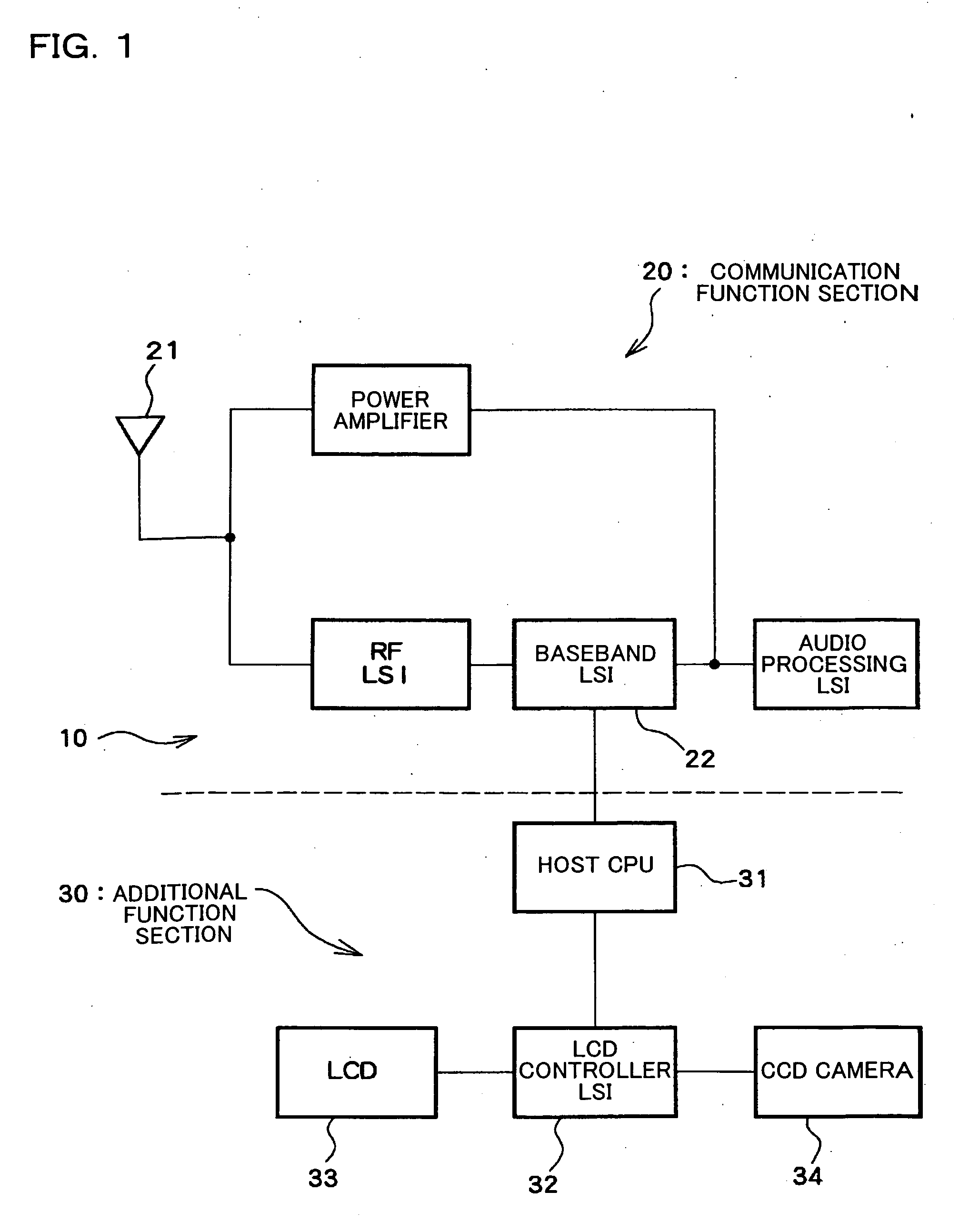
[0049]FIG. 1 is a block diagram of a portable telephone which is an example of an electronic instrument to which the present invention is applied. In FIG. 1, a portable telephone 10 is roughly divided into a communication function section 20 and an additional function section 30. The communication function section 20 includes various conventional blocks which process a signal (including a compressed moving image) transmitted and received through an antenna 21. A baseband LSI 22 (second integrated circuit) in the communication function section 20 is a processor which mainly processes voice or the like, and is necessarily provided in the portable telephone 10. The baseband LSI 22 is provided with a baseband engine (BBE), an application processor, and the like. Variable length code (VLC) encoding, scanning, AC / DC (alternating current / direct current component) predi...


PUM


Abstract

A moving image compression (or encoding) device including: a hardware processing section which compresses moving image data by hardware; a data storage section which stores the moving image data processed by the hardware processing section; and a software processing section which compresses the moving image data from the data storage section by software. The hardware processing section includes a plurality of processing sections which perform processing including a discrete cosine transform and quantization of the moving image data. The software processing section performs variable-length coding of the quantized moving image data.

Description

[0001] Japanese Patent Application No. 2003-150849, filed on May 28, 2003, is hereby incorporated by reference in its entirety. BACKGROUND OF THE INVENTION [0002] The present invention relates to a compression device which compresses a moving image using a Moving Picture Experts Group (MPEG) method or the like, and an imaging device using the same. [0003] In a conventional MPEG-4 compression (or encoding) / decompression (or decoding) device, the entire encoding / decoding is performed by hardware. [0004] In the case where the entire encoding / decoding is performed by hardware, the circuit scale is necessarily increased, whereby reduction of the IC size is hindered. If such a device is applied to a portable instrument such as a portable telephone, a demand for reduction of the size of the instrument cannot be satisfied. [0005] In the case where the entire encoding / decoding is performed by software, the load imposed on the CPU increases. Therefore, since the time necessary for the CPU to ...

Claims


Application Information

Patent Timeline
IPC IPC(8): H04N19/60G06F3/16G06K9/36H03M7/30H03M7/40H04N19/42H04N19/423H04N19/44H04N19/625H04N19/91
CPCH04N19/42
Inventor KONDO, YOSHIMASAKIMURA, TSUNENORI
Owner SEIKO EPSON CORP
Learn More