Method and apparatus for determining position of mining machine

a mining machine and position determination technology, applied in the direction of process and machine control, braking system, instruments, etc., can solve the problems of insufficient accuracy of the measuring method for the loader during loading, the method is not yet as efficient as manual loading, and the errors are small, so as to achieve the effect of determining rather accurately

Inactive Publication Date: 2005-05-24
SANDVIK TAMROCK
View PDF9 Cites 24 Cited by
  • Summary
  • Abstract
  • Description
  • Claims
  • Application Information

AI Technical Summary

Benefits of technology

[0007]An objective of the present invention is to provide a method and an apparatus enabling more accurate determination of the position of a mining machine as its wheels skid with respect to the surface.
[0011]The invention provides the advantage that when the wheels of the mining machine start skidding, the distance the machine has travelled and the direction and position thereof can be determined rather accurately in order to provide reliable automatic control of the machine during its return movement and a subsequent movement in the same direction. Another advantage that is evident particularly with loaders is that although transportation and unloading are preformed automatically, filling of the bucket is still remote-controlled manually, and the remote operator controlling the filling can thus concentrate solely on the filling. Furthermore, as soon as the filling of the bucket can be automated, the system will be ready for use and able to control the entire automatic operating cycle of a loader.

Problems solved by technology

In the prior art arrangement, the loader moves automatically between the locations and also empties the load from the bucket automatically, but during loading a remote operator controls the filling of the bucket via a telecommunications network since fully automatic loading of the bucket with the prior art methods is the prior art methods is not yet as efficient as manually controlled loading.
Although the obtained data is rather useful, it does contain some errors, wherefore the position of the apparatus must be checked in some other manner at suitable intervals.
However, the aforementioned measuring method is not sufficiently accurate for loaders during loading, when the bucket is being filled with broken rock.
Since the bucket must also be pushed into the pile of broken rock at a high speed, the wheels of the loader tend to skid and the loader may also deviate from the usual direction of travel during the filling of the bucket.
In such a situation, the dead reckoning method is subjected to errors, which cause problems in the automatic control of the apparatus.
Furthermore, at the training stage the environment of the loading site and particularly the direction of the material to be loaded may not have been observed and stored in full in the memory, since these matters usually change as the loading proceeds.
Correspondingly, problems also occur in the determination of the position of other mining machines by means of the dead reckoning method when one or more of the vehicles' wheels skid with respect to the underlying surface, thus causing errors in the determination.

Method used


Image

  • Method and apparatus for determining position of mining machine
  • Method and apparatus for determining position of mining machine
  • Method and apparatus for determining position of mining machine

Examples


Embodiment Construction

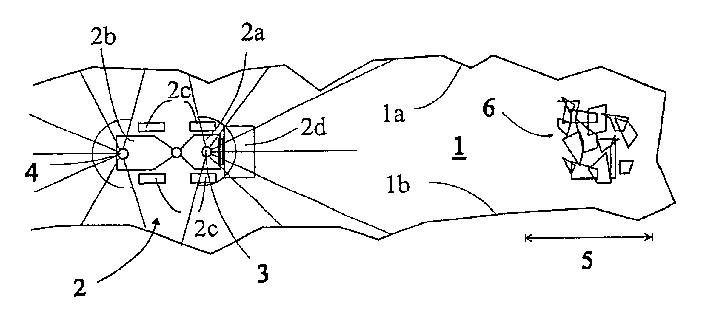
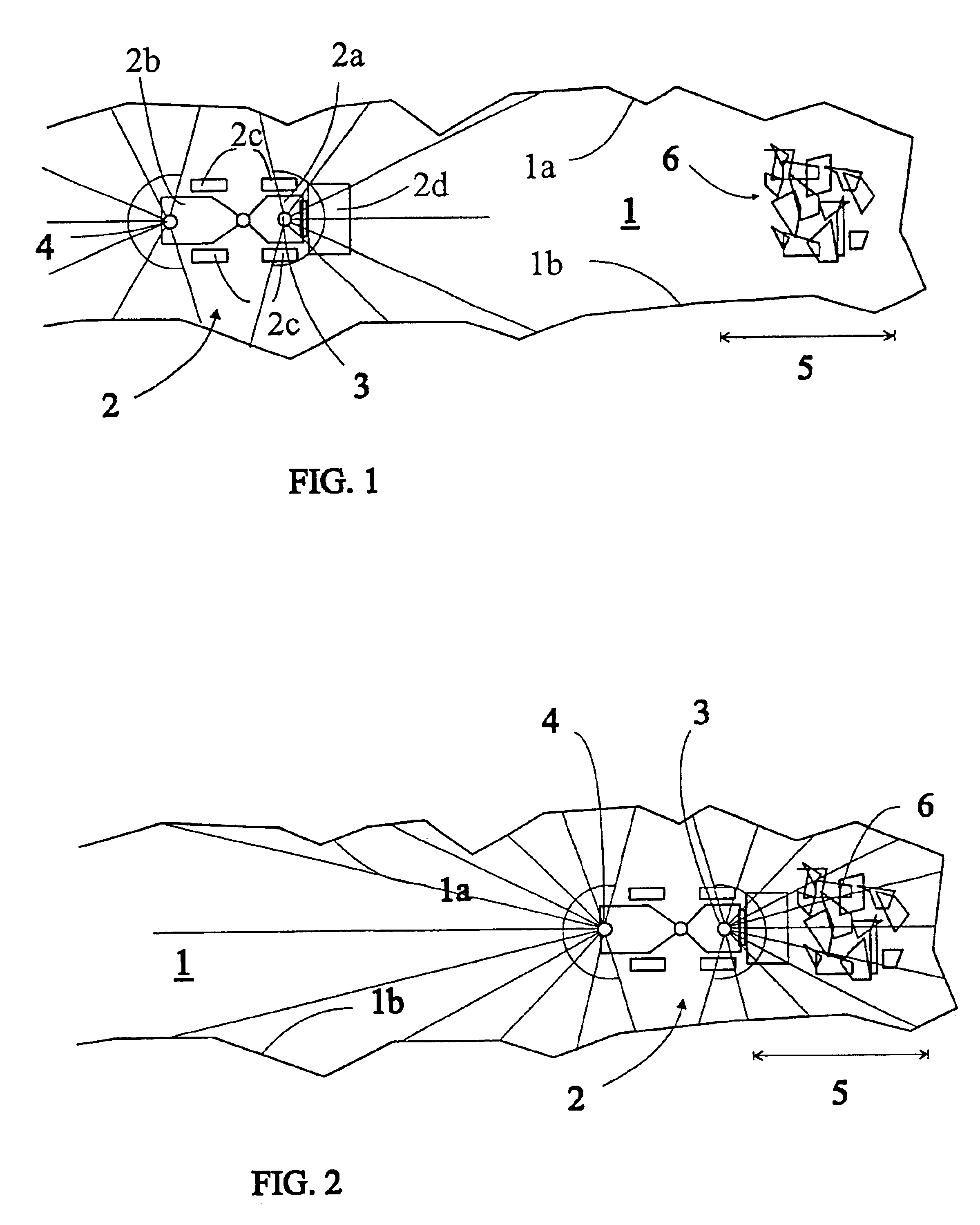
[0016]FIG. 1 shows a situation where a mining machine, in this case a loader 2, moving in a tunnel 1 approaches a loading site containing broken rock. The tunnel 1 is provided with lateral wall surfaces 1a and 1b. The loader 2 is typically of the frame-steered type and comprises a front frame 2a and a rear frame 2b, a pivoting joint between the frames, and wheels 2c fixed to each frame in a non-rotating manner. The loader is controlled by pivoting the front and the rear frame 2a, 2b with respect to one another. The front frame 2a is provided with a bucket 2d, onto which broken rock is loaded for transportation.

[0017]The top of the loader 2 is provided with measuring means 3, 4 arranged suitably to inspect the surfaces surrounding the route along which the loader 2 is moving, e.g. in a tunnel such surfaces are typically the wall surfaces 1a, 1b. The shape or profile and the distance of the surfaces from the loader 2 are determined as the loader moves along the route. The measuring me...


PUM


Abstract

A method and an apparatus for determining the position of a mining machine as its wheels skid with respect to the underlying surface. In the method, at least one detector detecting the operation of transmission detects skidding of at least one wheel with respect to the underlying surface, whereupon determination of the position by means of the rotation of the wheels and the direction of travel is interrupted. The apparatus includes at least one detector for detecting the operation of the transmission, the detector detecting the skidding of at least one wheel with respect to the underlying surface.

Description

CROSS-REFERENCE TO RELATED APPLICATIONS[0001]This application is a continuation of international PCT application Ser. No. PCT / FI02 / 00406, filed May 13, 2002, which was published in English as WO 02 / 093,282 A1 on Nov. 21, 2002, and which is incorporated by reference.TECHNICAL FIELD[0002]The invention relates to a method for determining position of a mining machine during skidding of at least one of the machine's wheels with respect to the underlying surface, the method comprising determining the position of the mining machine during its normal movement by measuring the distance the machine has moved in proportion to the rotation of the wheels and the direction in which the machine moves, further determining the position of the machine at suitable intervals over the route along which the machine is moving by determining profiles of wall surfaces surrounding the machine and by comparing the obtained wall surface profiles with wall profiles of corresponding points stored in a memory of ...

Claims


Application Information

Patent Timeline
Patent Type & Authority Patents(United States)
IPC IPC(8): G01C21/10G01C21/12G05D1/02
CPCG01C21/12G05D1/024G05D1/0272G05D2201/021G05D1/027
Inventor MAKELA, HANNUVON NUMERS, THOMAS
Owner SANDVIK TAMROCK
Why Eureka
Try Eureka