Manufacturing process to make a valve ball

Inactive Publication Date: 2005-05-31
HSIANG HUI CHIANG
View PDF2 Cites 26 Cited by
  • Summary
  • Abstract
  • Description
  • Claims
  • Application Information

AI Technical Summary

Benefits of technology

[0007]The present invention has a main object to provide a manufacturing process to make a ball valve which process is rapid and precise. The result wi

Problems solved by technology

However, this process costs more than others because it has to deal with epidermis chemical disposal and the spherical trimming procedure.
Besides, the residual chemical remained on the surface of the ball valve may harm human health.
This process is somewhat complicated due to its repeated punching activities and has to weld the hemispherical shapes together before removing of the upper and lower molds.
So that this process always cause great defective proportion, than other process.
However, this process requires twice

Method used


Image

  • Manufacturing process to make a valve ball
  • Manufacturing process to make a valve ball
  • Manufacturing process to make a valve ball

Examples


Embodiment Construction

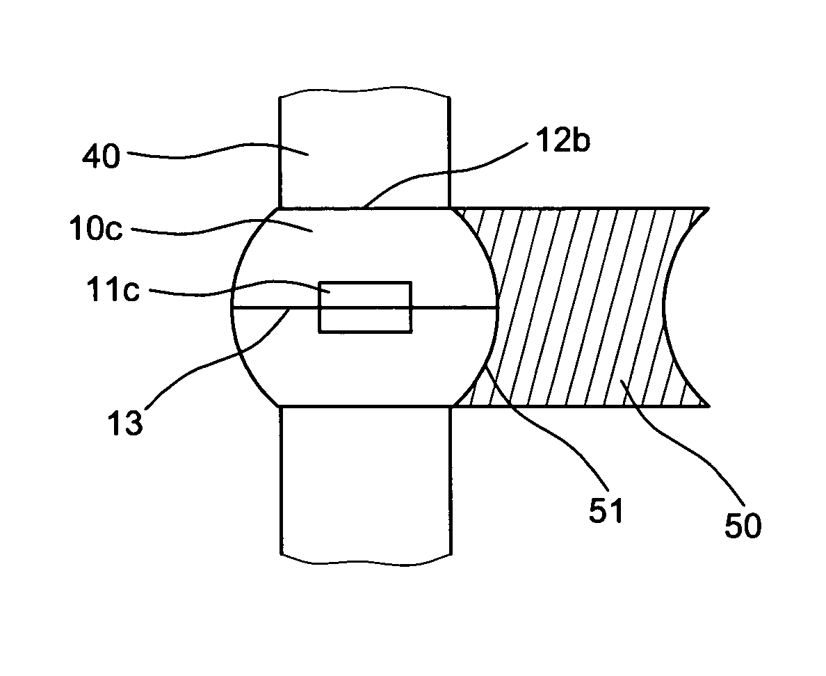
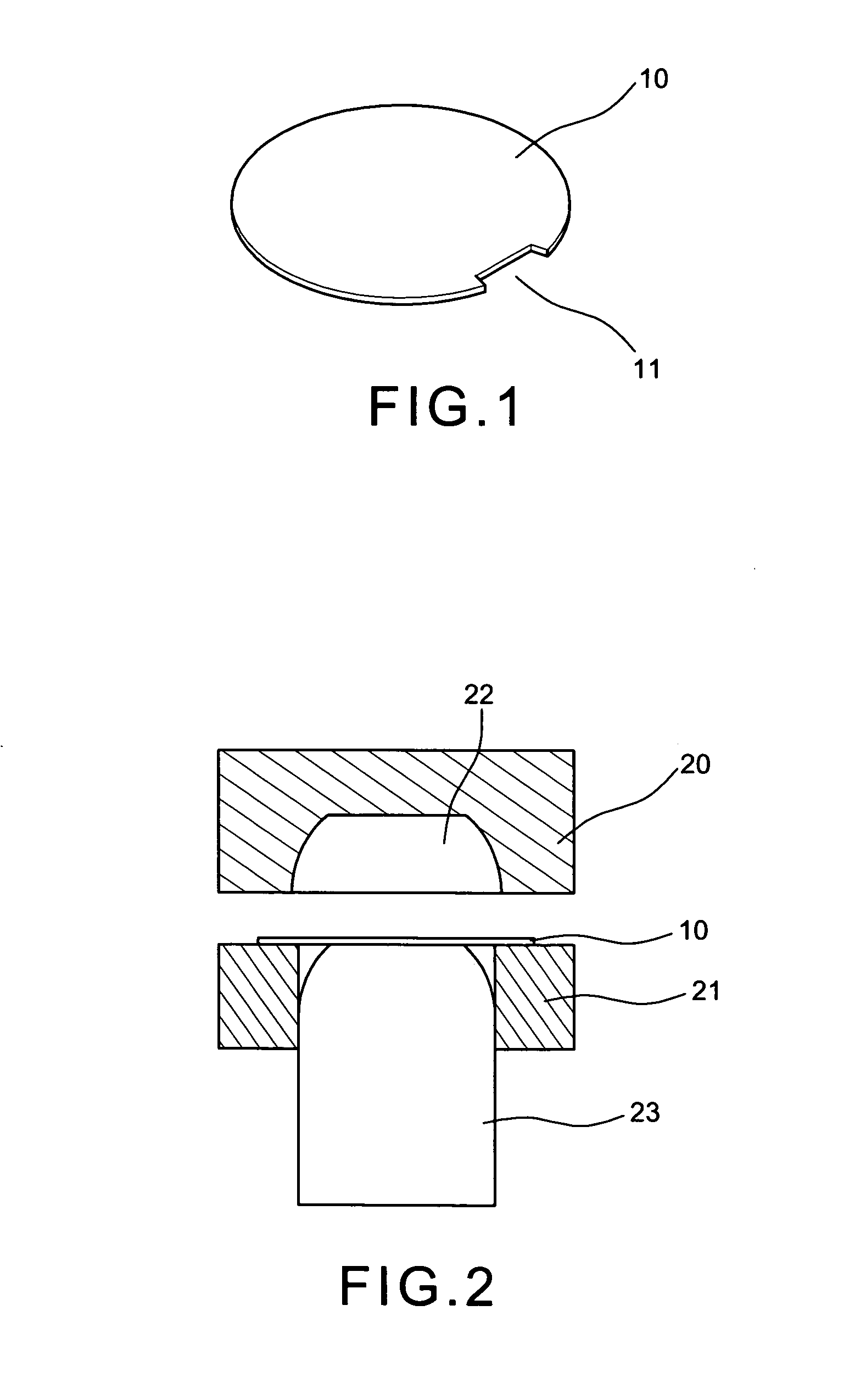
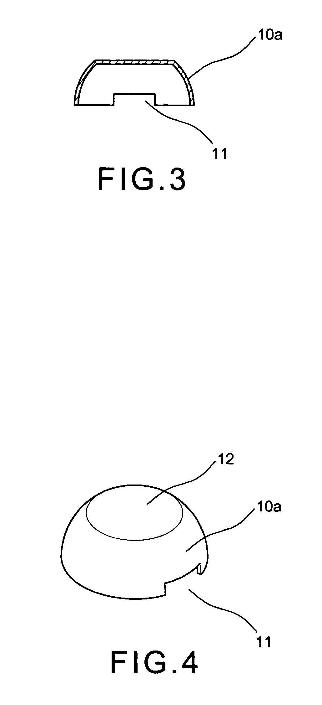
[0029]With reference to FIGS. 1 and 2 of the drawings, the manufacturing process to make a ball valve of the present invention comprises the following steps:[0030]a) prepare a pair of flat circular metallic plates 10 and each of the plates 10 has a roughly rectangular indentation 11 in a predetermined position of its circumference;[0031]b) put the flat circular metallic plate 10 on one by one basis, on a lower mold 21 which has a punch 23 slidably disposed in the center and incorporates with an upper mold 20 which is moving downward onto the plate 10. Then striking the punch 23 upward to form the circular plate into a bowl shape piece 10a due to that a bowl shaped depression 22 formed in the upper mold 20. The bowl shape piece 10a has an indentation 11 in a lower rim and a circular bottom 12 on the specific surface (as shown in FIGS. 3 and 4);[0032]c) place the bowl shape piece 10a into a semi-circular mold 30 (as shown in FIGS. 5 and 6), and use a sharp punch bar 31 to punch the bo...


PUM


Abstract

A manufacturing process to make a ball valve of the present invention includes the following steps: a) prepare flat circular metallic plates each of which has a rectangular indentation in a circumference; b) mold those plates into bowl shape; c) remove the circular bottom of the bowl shapes to reform a hemi-spherical shape by another mold; d) weld each pair of the hemi-spherical shapes into a spherical shape each of which has a pair of aligned openings and a lateral rectangular through hole; e) trim and grind the uneven connection seam; and f) polish and smooth the outer surface to finished a qualified ball valve which has uniform arc and thickness.

Description

BACKGROUND OF THE INVENTION[0001]The present invention relates to hydroelectric apparatus and more particularly to a manufacturing process to make a ball valve which is capable of rapidly and precisely to make shape of a ball valve.[0002]As we know that the ball valve is popularly used to the switches. The manufacturing process of the ball valve is categorized as forging, punching and / or roller ramming. FIG. 10 shows a prior art manufacturing process of a ball valve 70 which is adapting the roller ramming process by forging a pair of semi-spherical shapes 71 and welding them together into a ball shape and then making a central passageway by a punching bar. However, this process costs more than others because it has to deal with epidermis chemical disposal and the spherical trimming procedure. Besides, the residual chemical remained on the surface of the ball valve may harm human health. So that this process is now being abandoned.[0003]FIGS. 11, 12 and 13 indicate another prior art ...

Claims


Application Information

Patent Timeline
IPC IPC(8): B21K1/20B21K1/02B21K1/00B24B11/00B23P15/00F16K27/06
CPCB21K1/02B21K1/20F16K27/067B24B11/00B23P15/001
Inventor HSIANG-HUI, CHIANG
Owner HSIANG HUI CHIANG
Why Eureka
Try Eureka